(No.MB519)1-21
3.3 Cassette mechanism section
• Remove the cassette mechanism assembly. (See "3.1.3 Removing the cassette mechanism assembly".)
3.3.1 Removing the head amplifier & mechanism control board
(See Fig.1)
(1) After turning over the cassette mechanism assembly, re-
move the three screws A attaching the head amplifier &
mechanism control board.
(2) Disconnect the flexible wire from the connector CN31
on
the head amplifier & mechanism control board.
(3) Disconnect the head amplifier & mechanism control board
from the connector CN1
on the switch board and remove
the head amplifier & mechanism control board.
Reference:
Remove the solders from the section a to remove the parallel
wire soldered to the D.C. motor as required.
3.3.2 Removing the D.C. motor
(See Figs.1 to 4)
(1) From the bottom side of the cassette mechanism assem-
bly, remove the solders from the sections a. (See Fig.1.)
(2) From the top side of the cassette mechanism assembly, re-
move the two screws B attaching the D.C. motor. (See
Fig.1.)
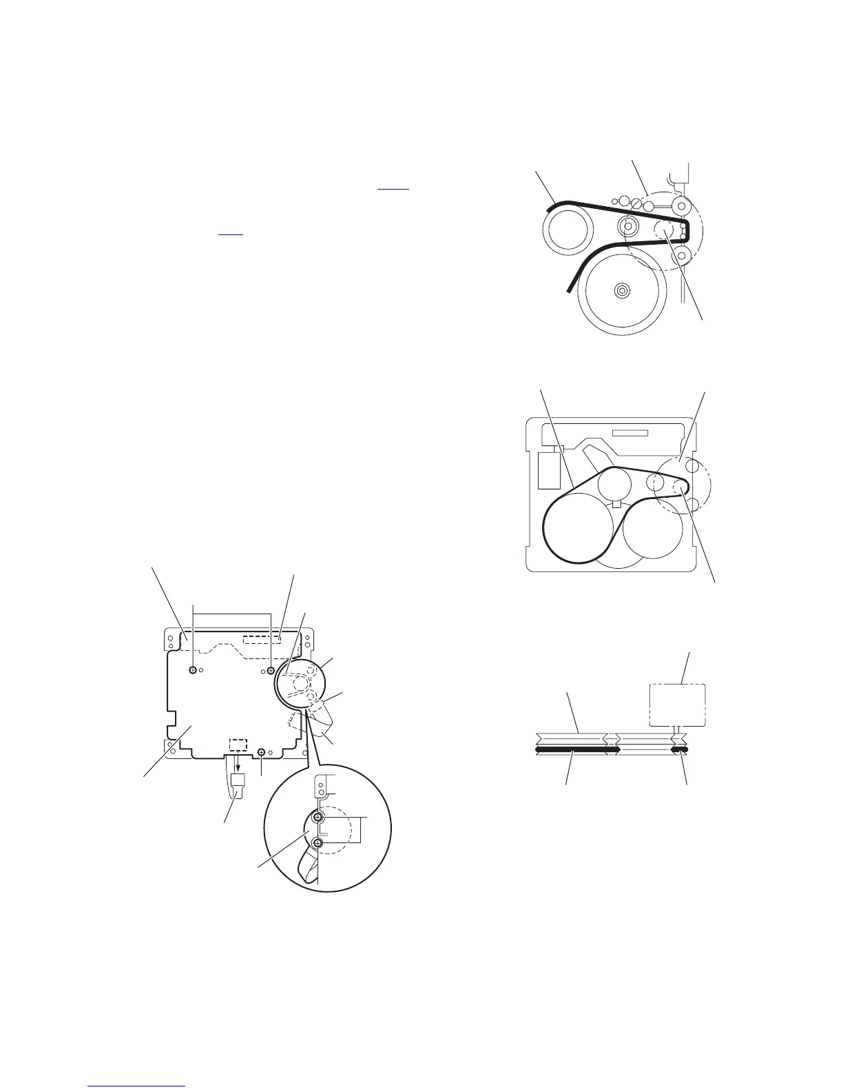
(3) While raising the D.C. motor, remove the capstan belt from
the motor pulley. (See Fig.2)
Caution:
Be sure to handle the capstan belt so carefully that this belt will
not be stained by grease and other foreign matter. Moreover,
these belts should be hanged while referring to the capstan
belt hanging method. (See Figs.3 and 4.)
Fig.1
Fig.2
Fig.3
Fig.4
A
A
Flexible wire
CN31
D.C. motor
Capstan belt
Head amplifier &
mechanism control
board
CN1
Switch board
Parallel wire
D.C. motor
a
B
Motor pulley
D.C. motor
Capstan Belt
Motor pulley
Capstan Belt
D.C. motor
Capstan Belt Motor pulley
Fly wheel (L)
D.C. moto
 Loading...