(No.YD091)1-15
4.2 Disassembly/assembly of the mechanism assembly
4.2.1 Introduction
The disassembly and assembly of the mechanism assembly should usually be performed in the ASSEMBLY mode.(Table 4-2-1)
Note that the mechanism is in the cassette in (C-IN) mode when the mechanism assembly is taken out of the set and that the C-IN
mode should be switched to the ASSEMBLY mode in this case.
To set the ASSEMBLY mode, apply 3 V DC to the electrodes on the upper part of the loading motor as shown in Fig. 4-2-7.
Table 4-2-1
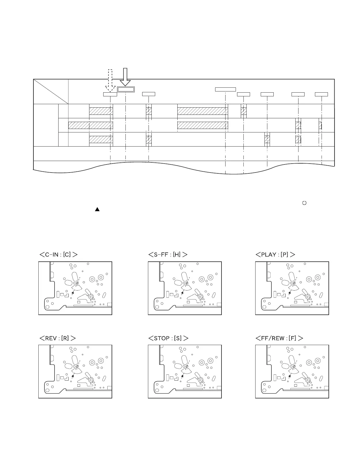
4.2.2 Mechanism modes
The mechanism has 6 modes as shown in Table 4-3-1. The current mode can be confirmed by the positioning of the " " marking on
the sub-cam gear and the " " marking on the mechanism. See the following figures (Figs. 4-2-1 to -6) for details.
Note:
• This mechanism assembly has another ASSEMBLY mode. However, this mode cannot be identified from the markings
because it corresponds to an intermediate position between the C-IN ( C ) mode and S-FF ( H ) mode. This mode can be
confirmed by the rotary encoder phase. See Fig. 4-2-7.
1. Checking the mechanism mode
R. ENC -20
ROTARY
ENCORDER
[
2
]
[
1
]
[
3
]
MAIN CAM GEAR 0
C-IN
ASSEMBLY
S. FF
LOADING END
PLAY REV STOP FF/REW
0
15
33.33
40
166.66
140
193.33
160
226.66
185
273.33
220
306.66
245
36
17
169.66
87
190.33
196.33
223.66
229.66
270.33
276.33
303.66
30.33
36.33
MODE
PARTS
[
H
][
C
]
[
H
]
[
P
]
[
F
][
S
][
R
]
Fig.4-2-1
Fig.4-2-4
Fig.4-2-2
Fig.4-2-5
Fig.4-2-3
Fig.4-2-6
 Loading...