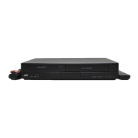
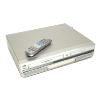
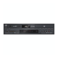
(No.YD091)1-33
4.10 Compatibility and error rate adjustment
4.10.1 Preparation
Before disassembly and adjustment, back up the data stored in
the EEPROM (IC1504 on the DV MAIN board) using the Service
Support System Software (SSS software).
Table 4-10-1 shows the important service points for the compat-
ibility and error rate adjustments.
Table 4-10-1
Note 1 :
• The linearity adjustment is required only after servicing
or replacing the drum or the take up/supply guide rail.
Note 2 :
• After replacing the DV MAIN board, write the original
data in the EEPROM of the new board. If write commu-
nication is not possible, mount the original EEPROM on
the new board.
When adjustments of more than one item are required, use the
following order for the adjustments.
4.10.2 Adjustment
The actual adjustment requires the following preparation.
4.10.2.1 Tools required for adjustment
Fig.4-10-1
4.10.2.2 Procedure
(1) Take out the 8 screws, then remove the top cover. (See
SECTION 3 DISASSEMBLY)
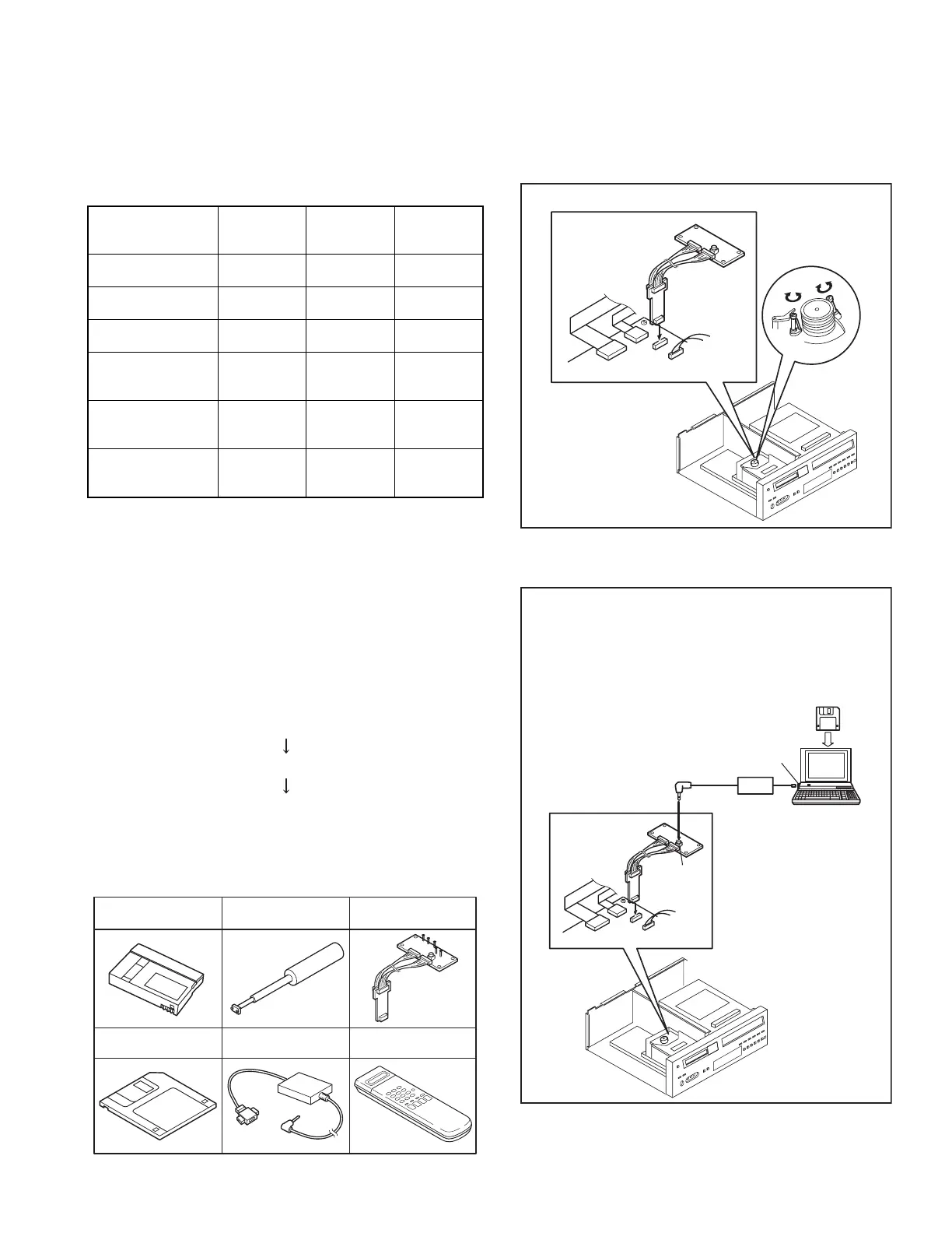
(2) Connect the jig connector cable to CN2001 on the DV
MAIN board.
Fig.4-10-2
4.10.2.3 Setup for computer adjustment
Fig.4-10-3
Linearity
adjustment
PB Switching
point
adjustment
Error rate
adjustmenmt
Drum
replacement
Required
Note 1
Required Required
Transport part
replacement
Required
Note 1
Not Check
Transport part
(drum) repair
Required
Note 1
Not Check
IC4001(PRE/REC
amp on DV MAIN
board) replacement
Not Not Check
IC2001(PB. EQ on
DV MAIN board)
replacement
Not Not Required
DV MAIN board
replacement
Note 2
Not Required Required
4.10.3 Linearity adjustment
4.10.4 PB switching point adjustment
4.10.5 Error rate adjustment
Alignment tape
US : MC-1
PAL : MC-2
SSS software
PTU94016-5
Guide driver
YTU94085
Jig connector cable
PTU94018B
PC cable
US : QAM0099-002
PAL : QAM0099-005
Jig RCU
PTU94023B
DV
MAIN PW
B
Jig Connector Cable
PTU94018B
CN2001
CN1501
CN1505
CN3701
D
V
MAIN PWB
C
N
2001
C
N
1501
C
N1505
C
N
3701
Service Support Software
RS-232C Port
PC Cable
Personal Computer
JVC
MENU
<JLIP>
-Setup by extending the jig connector-
Connect the Jig Connector Cable and setup the SSS software. It
automatically becomes the TCCS mode and "TCCS" is displayed
on the FDP.
To cancel the TCCS mode, press the CANCEL button of the remote
control unit.
The "TCCS" display on the FDP disappears.
 Loading...