XV-SA600BK/XV-SA602SL
19
3.8 Flap adjustment of the pick-up guide shaft
3.8.1 Tool list for adjustment
Stud (four pieces set)
Parts No. : JIGXVS40
Extension cord set (two cord and two board)
Parts No. : EXTXVS40CB
Hex wrench for adjustment
Off-the-shelf (1.3mm)
Test disc
VT-501 or VT-502
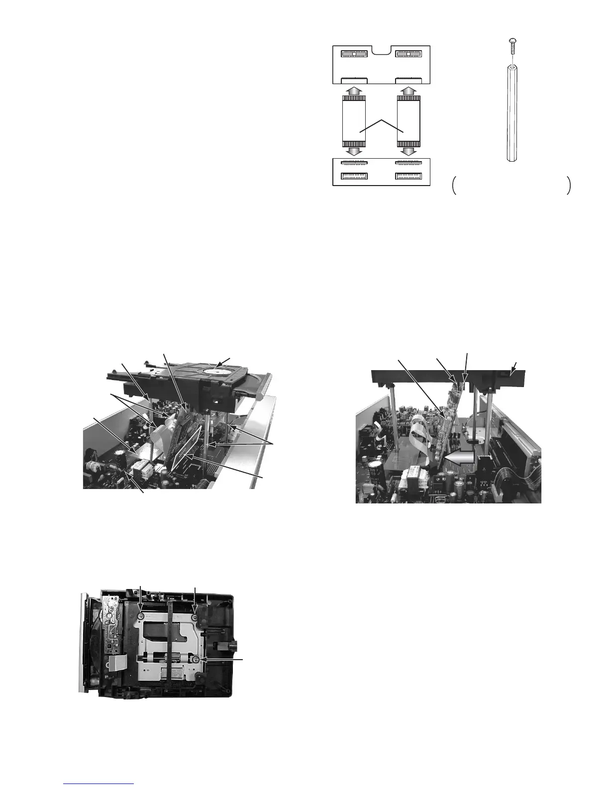
3.8.2 Adjustment preparation
(1) The mechanism assembly is made in the state from the main body from which is detached referring to the disassembly method.
(2) Three studs are installed in the mechanism assembly respectively.
(3) The servo control board is removed from the mechanism assembly, and puts into the state set up as shown in figure. (Each
wire connected by the servo control board this time leaves the connection maintained.)
Between shaft and hook of mechanism assembly of figure Board is put And, the board is inclined in the direction of the arrow
on figure as much as possible.
(4) The extension cord is inserted in the connector of the assistance board respectively.
The main board is connected with the servo control board as shown in figure.
3.8.3 Adjustment
(1) Puts into the state to display the jitter value on the FL display referring to "Display of the jitter value".
(2) The adjustment screw under the traverse mechanism is turned with hex wrench, and matches so that the jitter value displayed
on the FL display may become maximum value.
<POINT>
(1) Turns in the forward or the opposite direction, and makes to the position where the jitter value is good the half rotation of
adjustment screw a and b(180 degrees) respectively.
(2) Afterwards, adjustment screw b and c are turned in the same way, and makes to the best position.
XV-S40 CONTROL CONNECT
Assistance board
Connect to servo control board)
(Connect to main board)
Extension
cord
XV-S40
MAIN CONNECT
Stud
One is not used though it is on
set which consists of four units
Mechanism assembly
Stud
Stud
Servo control board
Assistance
board
Assistanc
board
Extension
cord
Main board
Mechanism assembl
Servo control board
Hook
Shaft
As this value is bigger, the jitter is more allowable in this model.
Adjustment screw a Adjustment screw b
Adjustme
screw c

 Loading...