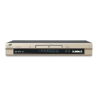
XV-SA600BK/XV-SA602SL
7
SECTION 2
Disassembly method
2.1 Main body
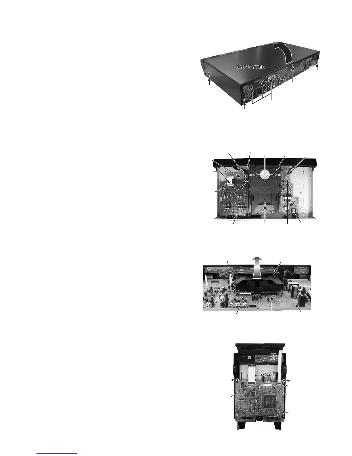
2.1.1 Removing the top cover (see Fig.2-1)
(1) Remove the two screws A attaching the top cover
on both sides of the body.
(2) Remove the three screws B attaching the top
cover on the back of the body.
(3) Remove the top cover from the body by lifting
the rear part of the top cover.
ATTENTION:
Do not break the front panel tab fitted to the top cover.
Fig.2-1
2.1.2 Removing the surround audio board (see Fig2-1,2-2)
• Prior to performing the following procedure,remove the top cover.
(1) Remove the three screws C attaching the surround audio
board on the rear panel.
(2) Disconnect the card wire from connector CN711 on the
surround audio board.
(3) The surround audio board is removed while picking up the
point of the fastener in two places.
Fig.2-2
2.1.3 Removing the mechanism assembly (see Fig2-2,2-3)
• Prior to performing the following procedure, remove the top cover.
• There is no need to remove the front panel assembly.
(1) Remove the three screws D attaching the mechanism
assembly on the bottom chassis.
(2) Remove the two screws E attaching the lug wire and main
board on the bottom chassis.
(3) The servo control board is removed from the
connector CN512 and CN513 connected with the main
board respectively.
(4) Remove the mechanism assembly by lifting the rear part
of the mechanism assembly.
Fig.2-3
2.1.4 Removing the servo control board (see Fig.2-4)
• Prior to performing the following procedure, remove the top
cover and mechanism assembly.
(1) Disconnect the card wire from connector CN201 and
CN202 on the servo control board respectively.
(2) Disconnect the flexible wire from connector CN101 on the
servo control board from pick-up.
< ATTENTION >
At this time, please extract the wire after short-circuited
of two places on the wire in part a with solder.
Please remove the solder two places of part a after
connecting the wire with CN101 when reassembling.
(3) Two places in hook b are removed, the servo control
board is lifted, and it is removed.
Fig.2-4
A x 2
B
C
B
B
D
D
JT102,JT103
CN4
Main board
Lug wire
Mechanism
assembly
E
E
Surround audio board
CN711
Fastener
CN513
CN512
Servo control board
Main board
Mechanism
assembly
ook b
Hook b
Servo contr
board
CN101
CN202
CN201
 Loading...