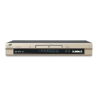
XV-SA600BK/XV-SA602SL
33
4.7 MN101C35DLJ (IC2) : System controller
4.7.1 Pin layout
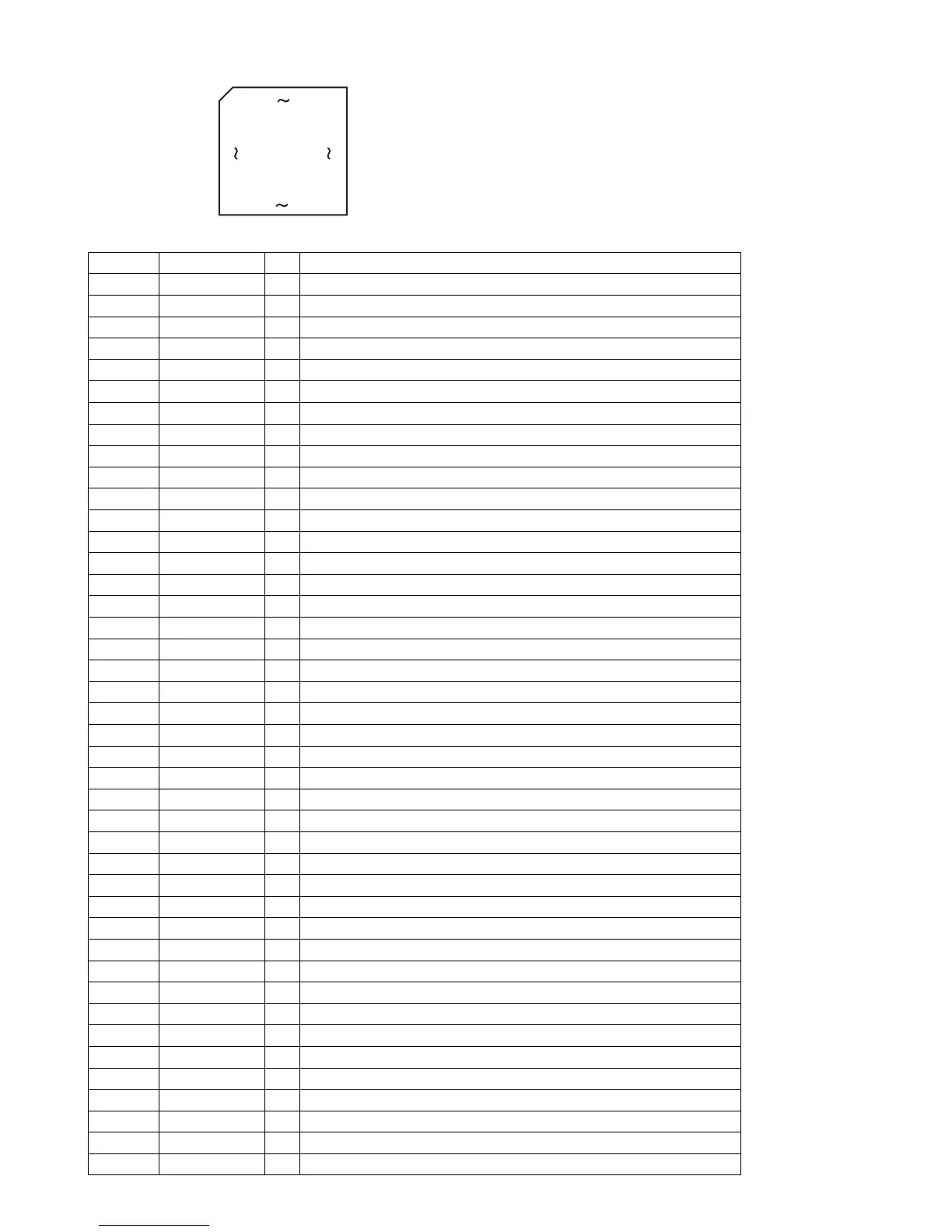
4.7.2 Pin function (1/2)
1
25
75
51
100 76
26 50
Pin No. Symbol I/O Description
1 RS232COUT - Unused
2 RS232CIN - Unused
3~7 NC - Unused
8 VDD - Power supply terminal (+5V)
9 OSC2 O Clock output terminal
10 OSC1 I Clock input terminal
11 VSS - Connect to ground
12 XI - Connect to ground
13 XO - Non connect
14 MMOD - Connect to ground
15 VREF- - Connect to ground
16 POWERSW I Power switch input terminal (S1)
17 NC - Non connect
18 NC I Destination switch (Ver.E and other version are judged. )
19 PROINT I SCAN mode switch detection input from S802
20 KEY1 I Operation switch detection input (S2,S3,S7)
21 KEY2 I Operation switch detection input (S4~S6)
22 RGB I RGB switch detection input from S801
23 NTB I NTB switch detection input from S801
24 VREF+ - Power supply terminal (+5V)
25 S500/SA600 I Model switch detect (S500 or SA600 is distinguished. )
26 RESET I Reset input terminal
27 AVCO O AV Compulink output terminal
28 AVCI I AV Compulink input terminal
29 POWERON O Power ON signal output
30 TCLOSE O Tray close instruction output terminal
31 TOPEN O Tray open instruction output terminal
32 LMMUTE O LMMUTE signal output
33 SWOPEN I Tray open switch detection signal input terminal
34 SWUPDN I Elevator UP/DOWN switch detection signal input terminal
35 REMO I Remote controller signal input terminal
36 NC - Non connect
37 CS I Serial communications interrupt input
38 NC - Non connect
39 TXD O Serial communications data output
40 RXD I Serial communications data input
41 SCK I Serial communications clock input
42 INT O Serial communications interrupt output
43 NC - Non connect
44 RESET O LSI reset signal output
45 DISCSET O Mechanism state signal output
46 DISCSTP I Mechanism state signal input
 Loading...