XV-SA600BK/XV-SA602SL
34
4.7.3 Pin function (MN101C35DLJ 2/2)
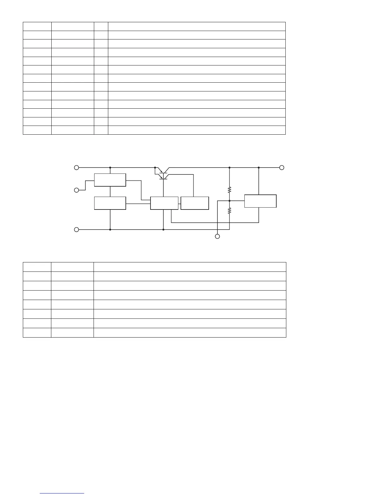
4.8 MM1565AF-X (IC951) : 500mA Regulator
4.8.1 Block diagram
4.8.2 Pin function
Pin No. Symbol I/O Description
47 P67 O Standby LED control signal output (RED)
48 P66 O Standby LED control signal output (GREEN)
49 P65 O Progressive LED control signal output (RED)
50 P64 O Progressive LED control signal output (GREEN)
51 P63 O DVD Audio LED control signal output (BLUE)
52~64 P62~P70 O FL Grid control signal output
65~88 P87~PB3 O FL Segment control signal output
89~91 NC - Non connect
92 INT/PRG - Unused
93 MUTE O Audio muting control signal output
94~99 NC - Non connect
100 VPP - Power supply terminal for FL display
Bias
Thermal
shutdown
Driver
Current
limiter
Reference
Vin
ont
ND
Cn
V
Pin No. Symbol Function
1 Vout Output terminal
2 NC Non connect
3 GND Connect to ground
4 Cn Noise decrease terminal
5 Cout Control terminal
6 Sub Substrate (Connect to ground)
7 Vin Input terminal
 Loading...