17
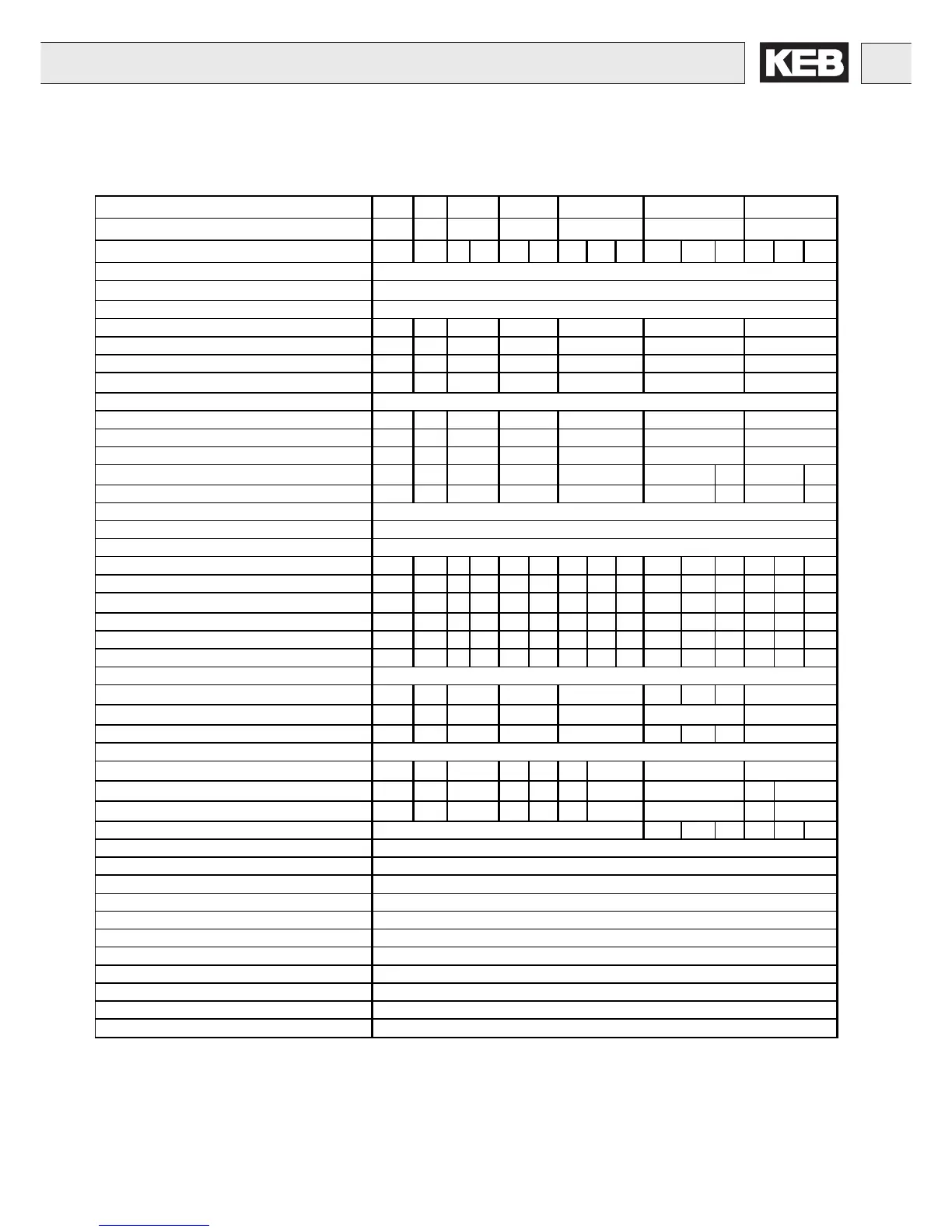
2.2 Technical Data 460V Class
Technical Data
1) The wire gauge is based on the maximum fuse rating, copper wire with minimum 75°C insulation rating, THHW or equivalent.
If branch circuit protection is selected based on rated input current, the wire size could be reduced.
2) With the regulated systems F5-M as well as F5-S 5% must be subtracted as control reserve
3) Rated operation means, rated input voltage, rated output current, and rated carrier frequency.
4) This data is only valid for units with internal brake transistor GTR 7 (see "unit identification")
5) With units with integrated EMI filter the distance is less:
up to max. 5m line length and 4kHz operating frequency = Limit Value B (EN 55011)
up to max. 10m line length and 16kHz operating frequency = Limit Value A (EN 55022)
Inverter Size 05 07 09 10 12 13 14
Recommended Motor Power [hp] 1/2 1 2 3 5 7,5 10
Housing size B B B D B D B D E D E G D E G
Input Ratings
Supply voltage
[V]
305...500 ±0 (460 V Nominal voltage
4)
)
Supply voltage frequency [Hz] 50 / 60 +/- 2
Input phases 3 3 3 3 3 3 3
Rated input current [A] 1,4 2,5 4,8 6,7 11 15 20
Recommended maximum input fuse [A] 15 15 15 15 20 25
Recommended wire gauge
1)
[awg] 14 14 14 14 12 10
Output Ratings
Rated output power [kVA] 0,9 1.8 2,8 4.0 6.6 8.3 11
Rated motor power [kW] 0,37 0.75 1,5 2,2 4.0 5.5 7,5
Rated output current [A] 1.0 1.8 3.4 4.8 7.6 11 14
Peak current (30 seconds)
2)
[A] 2.3 4.7 7.4 10.4 17 18 29,7 24,8
Over current fault (E.OC) trip level [A] 2.8 5.6 8.9 12.5 21 21.6 35,6 29,7
Overload curve (see annex) 1
Output voltage [V] 3 x 0…V Line
Output frequency [Hz] Generally 1600Hz however it is limited by the switching frequency
Rated switching frequency [kHz] 16 16 8 8 8 16 4 8 16 4 8 16 2 8 16
Maximum switching frequency [kHz] 16 16 16 16 16 16 4 16 16 16 16 16 4 16 16
Power loss at rated operation
3)
[W] 60 90 80 105 120 170 150 185 300 185 250 200 185 320 260
Stall current at 4kHz [A] 1,3 2,6 4,1 4,1 5,8 5,8 7,6 9,5 9,5 12 12 12 14 16,5 16,5
Stall current at 8kHz [A] 1,3 2,6 4,1 4,1 5,8 5,8 – 9,5 9,5 9,5 12 12 - 16,5 16,5
Stall current at 16kHz [A] 1,3 2,6 3,5 3,5 4,9 5,8 – 5,8 9,5 5,8 12 12 - 10 12
Braking Circuit
Min. braking resistance
4)
[Ohm] 390 120 120 82 82 56 39 50
Typ. braking resistance
4)
[Ohm] 390 390 270 270 150 100 82
Max. braking current [A] 2.2 7.5 7.5 10 10 15 21 15
Installation Information
15 20 100 100 65 – 330 300 - 330
Tightening torque for terminal strip [in lb] 4.5 4.5 4.5 11 4.5 4.5 11
Environme ntal
Max. heat sink temperature TOH [°C] 90°C / 194°F
Storage temperature [°C] -25...70 °C / -13…158°F
Operating temperature [°C] -10...45 °C / 14…113°F
Housing design / protection Chassis / IP20
Relative humidity max. 95% without condensation
Approvals
Tested in accordance with… EN 61800-3 /UL508C
Standards for emitted interference EN 55011 Class B / EN 55022 Class A
Standards for noise immunity IEC 1000-4-2 / -3 / -4 / -5/ -6
Climatic category 3K3 in accordance with EN 50178
20
12
39
21
21.6
25.9
 Loading...


