31
95080402
07.F5.S0C-1220
L1
L2
L3
+
-
PB
U
V
W
Not
for PC
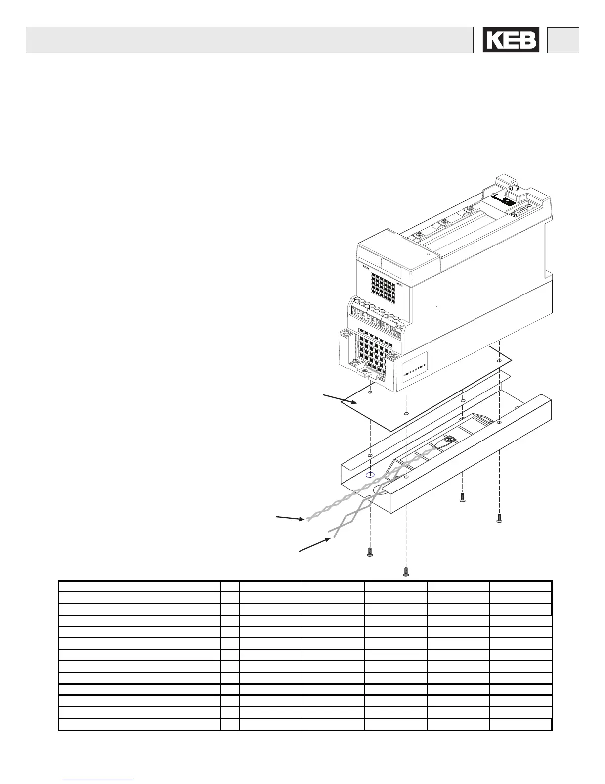
3.1.4 Back Mount Braking Resistor
Metal cover
Connection for thermal sensor (white)
(Terminals T1/T2)
Connection braking resistor (red)
(Terminals ++/PB)
Accessories
The inverter mounted braking resistor is designed with space savings in
mind. The resistor is mounted directly under the heatsink of the inverter.
The heat generated flows vertically out the top of the unit. It should be
used only in applications where the braking time is kept to a minimum.
The resistor kit consists of:
- Braking resistor
- Temperature sensor
- Mounting hardware
Use with 230V inverters size 07,09 10 09,10,12 13 14
Use with 460V inverters size 07,09,10 10,12 10,12,13,14 12,13,14, 13,14,15
Housing B B D E E
Braking resistor
[
Ω
]
160 82 82 60 60
Continuous power dissapation [W] 35 35 35 60 2 x 60
One time peak power (max. 3s) 230V [W] 900 1700 1700 2400 2400
One time peak power (max. 3s) 460V [W] 3400 6650 6650 9100 9100
Power at 5% d.c.f. [W] 700 700 700 1200 2400
Power at 10% d.c.f. [W] 350 350 350 600 1200
Power at 20% d.c.f. [W] 175 175 175 300 600
Power at 40% d.c.f. [W] 90 90 90 150 300
Weight lb 2 2 2 3 3.5
Partnumber of the kit
09.F5.B90-0300 12.F5.B90-0300 12.F5.D90-4300 14.F5.E90-4300 15.F5.E90-4300
 Loading...


