39
3.3 Output Filters
3.3.1 Motor Choke
Accessories
There are several reasons to install a choke between the inverter and the motor. These reasons depend
on the following variables: operating voltage, inverter size, motor type, motor cable type (shielded or not)
and motor cable length. The conditions around the usage of the chokes are described below.
Shielded motor cables are recommend to reduce the possibility of noise interfering with other
components, i.e. sensors, controllers. However by shielding the wires, a good capacitance coupling
to earth ground is created. As the motor cable length increases, the coupling capacitance increases,
resulting in higher ground leakage currents and higher levels of conducted EMI on the line. As a result,
with longer shielding cables the inverter and KEB EMI filter may no longer comply with the EN norm
regarding conducted interference. Thus it is necessary to use a motor choke to reduce these levels.
If the inverter is rated for 1, 2 and 3 hp and it is operated with a high carrier frequency, it may be necessary
to use a motor choke even with relatively short cable lengths. Capacitive current flows between the
motor leads U,V,W and to ground via the shield, as a result adding to the motor current. The resulting
current typically exceeds the rated current of the inverter causing nuisance over load or over current
faults. This does not effect the larger hp units since the capacitive current is proportional to the cable
length and is roughly the same for all sizes of inverters.
When the motor cables are 100 to 150 feet in length, voltage peaks several times greater than the rated
voltage of the motor can begin to appear at the motor. By using motors which have a high insulation
breakdown rating, usually listed in volts (1600V or higher), the choke can be eliminated. However, if
standard motors with normal insulation ratings are used, the choke is highly recommended.
Finally, as the motor cables become longer, it is possible for voltage peaks to appear at the motor and
the inverter's terminal strip. In this case the motor windings may have a high insulation rating protecting
the motor, but the inverter has only a 1200V rating on the power IGBTs. As a result a motor choke is
always recommended when the cables are longer.
Taking all these factors into consideration, the maximum cable length, per inverter size and carrier
frequency is listed in the tables on pages 15-20. For cable lengths greater than list a choke is
recommended.
Choke sizing-motor chokes should be selected such that the rated current of the choke is equal to or
greater than the rated current of the inverter. Three percent chokes are sufficient. However, 5% chokes
will reduce the audible PWM noise in the motor when operating at lower carrier frequencies.
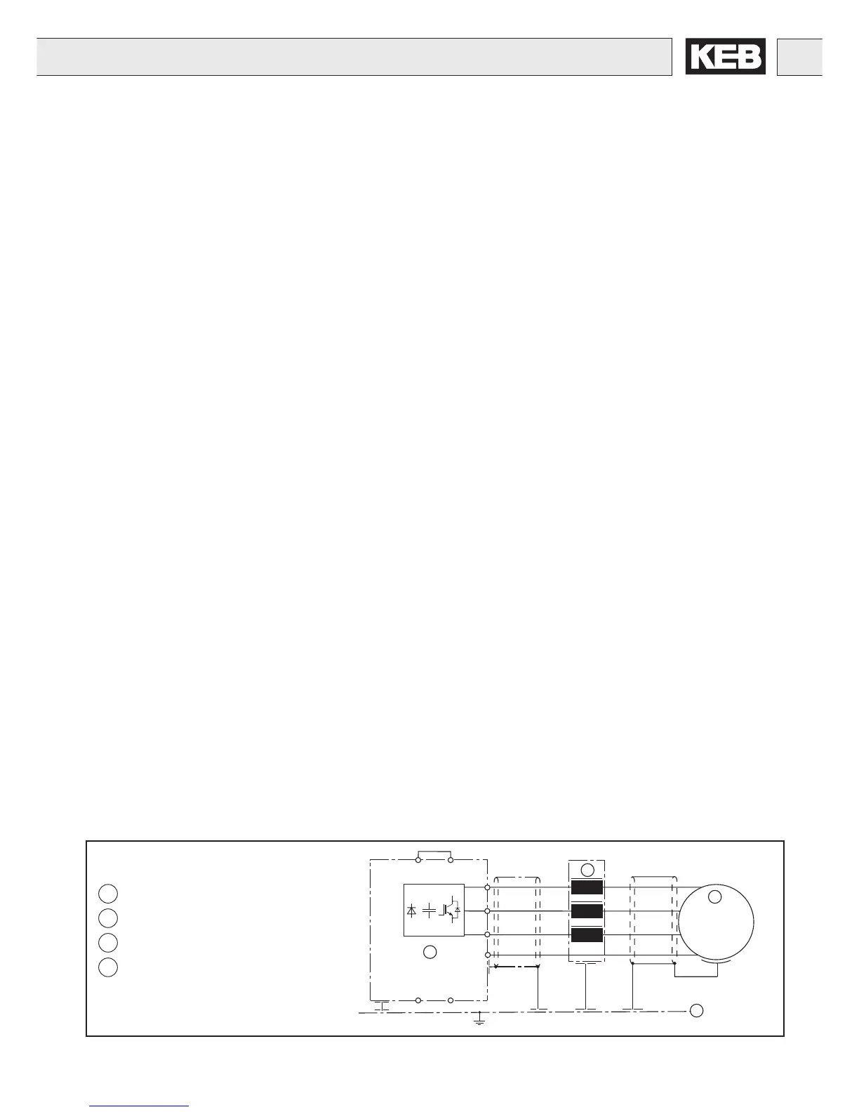
Connection of the motor choke
5
KEB COMBIVERT
6
Motor choke
7
Motor
8
Sub panel in control cabinet
U
V
W
GND
M
3
~
T1
T2
U1
V1
W1
U2
V2
W2
+ +
PB
+
5
7
8
6
GND
 Loading...


