Wiring example in PTC mode
Mixed sensor chain
T1
T2
Table 17: Wiring example in PTC mode
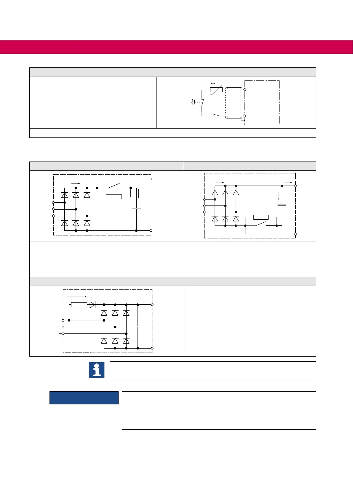
6.5 Input and pre-charging circuits
Type A1: AC / DC drive converter Type A2: AC / DC drive converter
+
++
--
L1
L2
L3
Ipre
Iext
IAIC
+
+
-
L1
L2
L3
Ipre
IAIC
Iext
Type A1 or A2 can be supplied by mains and by DC circuit. The starting current limiting is designed after
the input terminals. When used as output, parallel connected drive converters must have an own starting
current limiting at the DC voltage input. The maximum charging current must be observed!
Type D1: AC drive converter
+PA
-
L1
L2
L3
+
Rv
Ipre = IAIC
Iext
Type D1 can be supplied by mains. In consid-
eration of the DC link capacity the DC voltage
terminals can be used as output. When used as
input ensure that the starting current is external-
ly limited.
=> „Dimensioning“ .
NOTICE
Leakage capacitors against earth in the DC link
Drive converters with leakage capacitors in the DC link against earth
are not allowed for F5-AIC operation and can be destroyed. Only re-
leased units by KEB may be connected.
42
CONNECTION OF THE COMBIVERT F5-AIC
 Loading...


