4 Unit Data
Information on the dimensioning => „Dimensioning“.
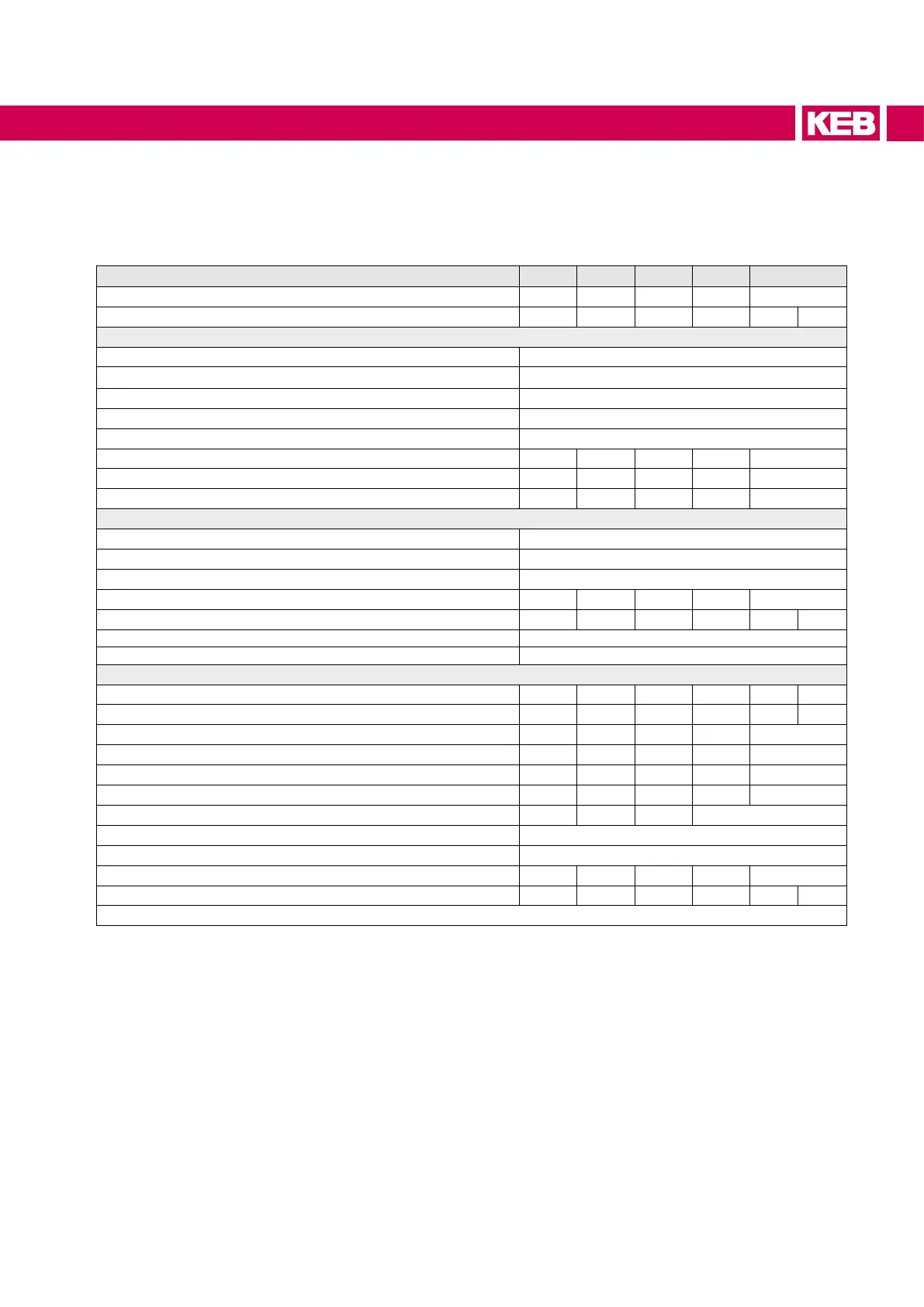
Device size 14 16 18 20 22
Housing size E G H R R
Cooling mode (L=air; W=water) L L L L L W
Input data
Mains phases 3
Permitted mains forms
1)
TN system
Rated input voltage U
N / V 400
Input voltage range U
in / V 340…480 ± 0%
Mains frequency f
N / Hz 50 / 60 ± 2
Rated input power S
N / kVA 11 23 35 52 80
Rated input current I
N / A 16.5 33 50 75
2)
115
2)
Max. permissible mains fuse type gR / aR
25 50 80 100 160
Output data
Rated output voltage U
outN_dc / V 680
Output voltage range
3)
U_dc / V 530…840
Overvoltageswitch-o(E.OP) U
OP_dc / V 840
Power supply/regenerative rated current
4)
IoutN_dc / A 16.5 33 50 75 115
Max. regenerative DC current 30 s I
out_max_dc / A 29.7 49.5 75 112 172 207
Rated switching frequency
5)
fSN / kHz 8
Max. switching frequency f
S_max / kHz 16
Other data (referring to the rated data)
Overcurrentcut-o(E.OC) I
OC / % 216 180 180 180 180 216
Overload current (E.OL) 30 s I
OL / % 180 150 150 150 150 180
Max. permissible DC link capacity C
ext / mF – – – 50 50
Max. AIC charging current (=> 6.5) I
AIC / A 29
6)
57 29 226 226
Max. external charging current (=> 6.5) I
ext / A 75
6)
135 322 – –
Max. permissible total charging current (=> 6.5)
Ipre / A 104
6)
192 351 226 226
Mains input circuit (=> 6.5) Type A1 A2 A1 D1
Permissible DC fuses => „DC fuses“
Short-circuit factor at the connection point (S
kn / SN) 15 < S
kn“ < 350
Power dissipation at rated operation P
BR / W 295 449 525 830 1400
Max. heat sink temperature t
_max / °C 90 90 90 90 90 60
Table 7: Device data
1)
Operation on a local limited IT system with sine-wave EMC lter is possible.
2)
The input current of the drive converter is limited, if necessary to the rated current of the AIC / LCL
lter.
3)
The operation is dependent on the voltage setpoint and the UOP limit (=> Programming manual).
4)
Measured at a reference voltage of 680 V DC.
5)
Must be set to 8 kHz for AIC operation (factory setting 4 kHz) !
6)
At ambient temperature Ta of 45°C.
27
UNIT DATA