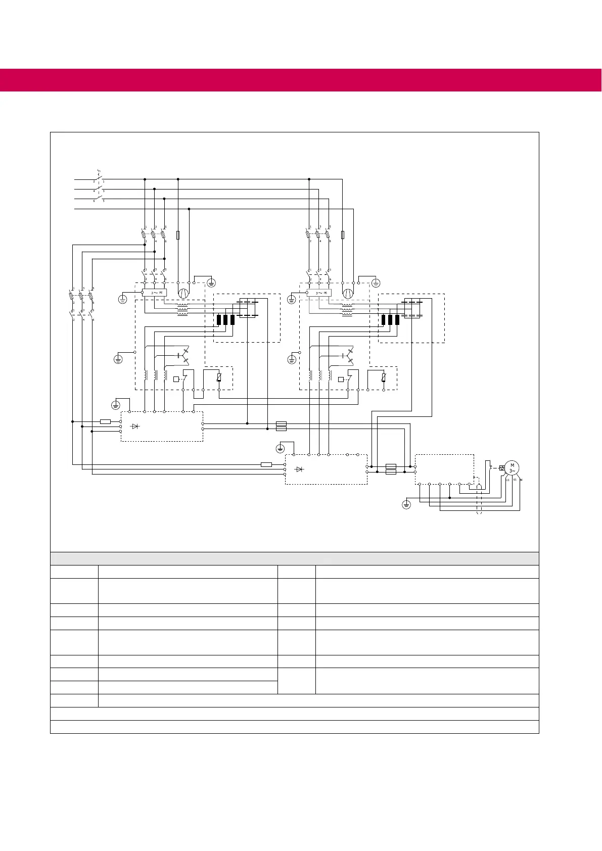
6.6.4 Circuit example for the master-slave operation with AIC/LCL lter and common mode lter
-Q1
-F1
L1
L2
L3
-F5
-K2
1) U V W
PE
-U5
-U1
-U3
-K3
U1.2
V1.2
W1.2
U1.3
V1.3
W1.3
+UZK -UZK
L1 L2 L3
-S6
°C
T1 T2 KTY+ KTY-
+
KTY
L N PE
N
V W
PE
-U6
-U2
-U4
-K4
U1.2
V1.2
W1.2
U1.3
V1.3
W1.3
+UZK
-UZK
L1 L2 L3
-S6
°C
T1 T2 KTY+ KTY-
+
KTY
L N PE
-F3
U V T1 T2WPE
-U7
+PA
-
L1
L2
L3
Master
U V T1 T2WPE
-U8
+PA
-
L1
L2
L3
Slave
T1 T2U V W PE
-U9
+
-
-S7
-G1
Rv1
Rv2
-F6
-F7
-F8
-F9
-F2 -F4
1) U
Legend
Q1 Main switch G1 Motor
F1, F2 Main fuses
2)
S6
Temperature detection NC contact and KTY84
sensor
3)
F3, F4 Fan fuse S7 Motor temperature switch
F5 Pre-charging fuses 20 A (slow) U3, U4 Commonmodelter
F6, F7
F8, F9
DC fuses
2)
U7,
U8
COMBIVERT F5-AIC
K3, K4 Main contactor U9 Drive converter
K2 Pre-charging contactor
U5, U6 LCLlter
Rv1, Rv2 Pre-charging resistors
U1, U2 EMClter(integratedintoU4uptosize24)
Fan control => Programming manual
Figure 11: Circuit example for the master-slave operation with AIC/LCL lter and common mode lter
1)
Output terminals U, V, W for size 26 and 29 => U2, V2, W2
2)
Mains and DC fuses must be monitored.
3)
Design dependent on lter size. Attention, observe polarity !
46
CONNECTION OF THE COMBIVERT F5-AIC
 Loading...


