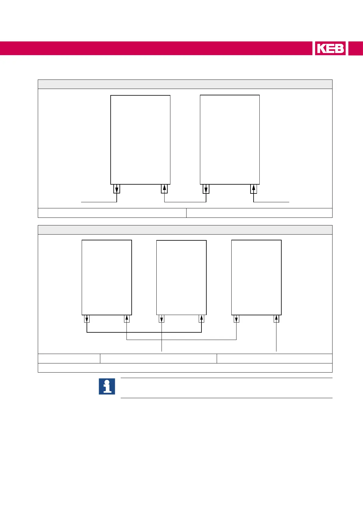
10.1.5.2 Connection scheme for a cooling circuit (series connection)
Coolant connection for a master / slave system
F5/F6
Master
F5/F6
Slave
Coolant outlet Coolant inlet
Coolant connection for a master / slave / slave system
F5/F6
Master
F5/F6
Slave 2
F5/F6
Slave 1
Coolant outlet Coolant inlet
Figure 28: Coolant connection
This connection scheme is only an installation proposal and does not replace
professional planning and execution!
If the drive converter system operates at rated operation, the coolant circuit can be done
in a series connection. It should be noted that the temperature is analog measured in the
slavemodulesandanerrorsignalisgivendigitallytothemaster.Thewaterreturnow
should always be attached at the master in order to display real temperatures.
The heat power dissipation for each device size can be found in the technical data. The
resultingvolumeowhastobeintherecommendedoperatingrangeofthetemperature
dierence(=>„Volume ow in dependence of the heat power dissipation and tempera-
ture dierence“).Therelationshipsbetweenheatpowerdissipation,owandtemperature
dierence=>„Volume ow in dependence of the heat power dissipation and temperature
dierence“.
67
COOLING SYSTEM
 Loading...


