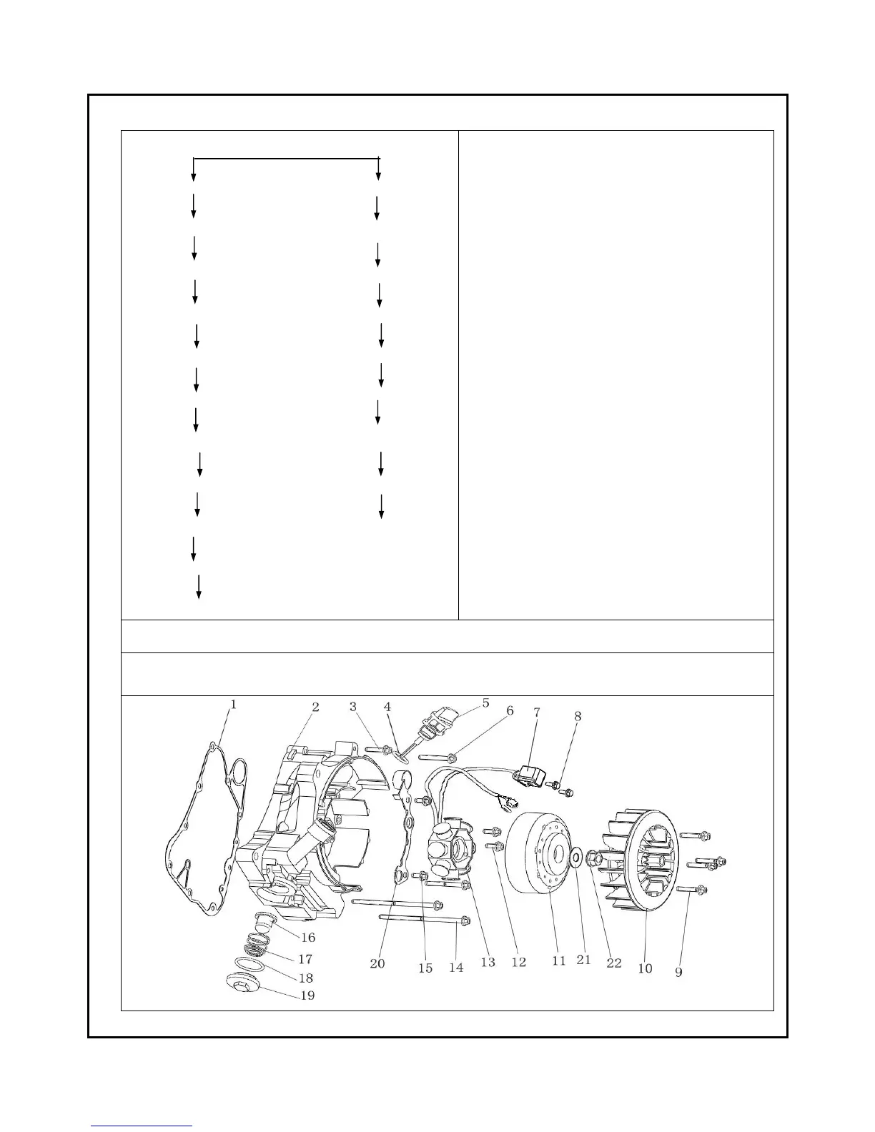
f . R I G H T C R A N K C A S E C O V E R A C C E S S O R I E S I N S TA L L AT I O N
REMOVAL:
::
:
Screw (9) filter net screw cap(19)
Fan assy.(10) O-ring(18)
Nut (22) spring(17)
Gasket(21) filter net assy.(16)
Flywheel assy.(11) fuel gauge(5)
Screw(8) seal ring(4)
Trigger assy.(7) other bolts
Bolt(15) ring crankcase cover(2)
Clip holder (20) gasket (1)
Bolt (12)
Magneto stator (13)
nut(22) 50N.M
Magneto bolt (2) 7N.M
Fan bolt (9) 11N.M
Trigger screw (8) 6N.M
Filter net screw cap (19) 57N.M
Other bolts for right crankcase 11N.M
The installation sequece is the reverse of removal.
NOTICE:
::
:1. The clearance between flywheel trigger and trigger head is 0.5±0.2mm.
2. Fan and trigger head cannot collide.
 Loading...