Strap(14)/driven disc assy.(10)
Bush(3)/driver wheel assy.(2)
Starting driven sprocket(1)
Starting spring slice(9)
Kicking starter gear assy.(8)/starting transition
gearassy.(7)
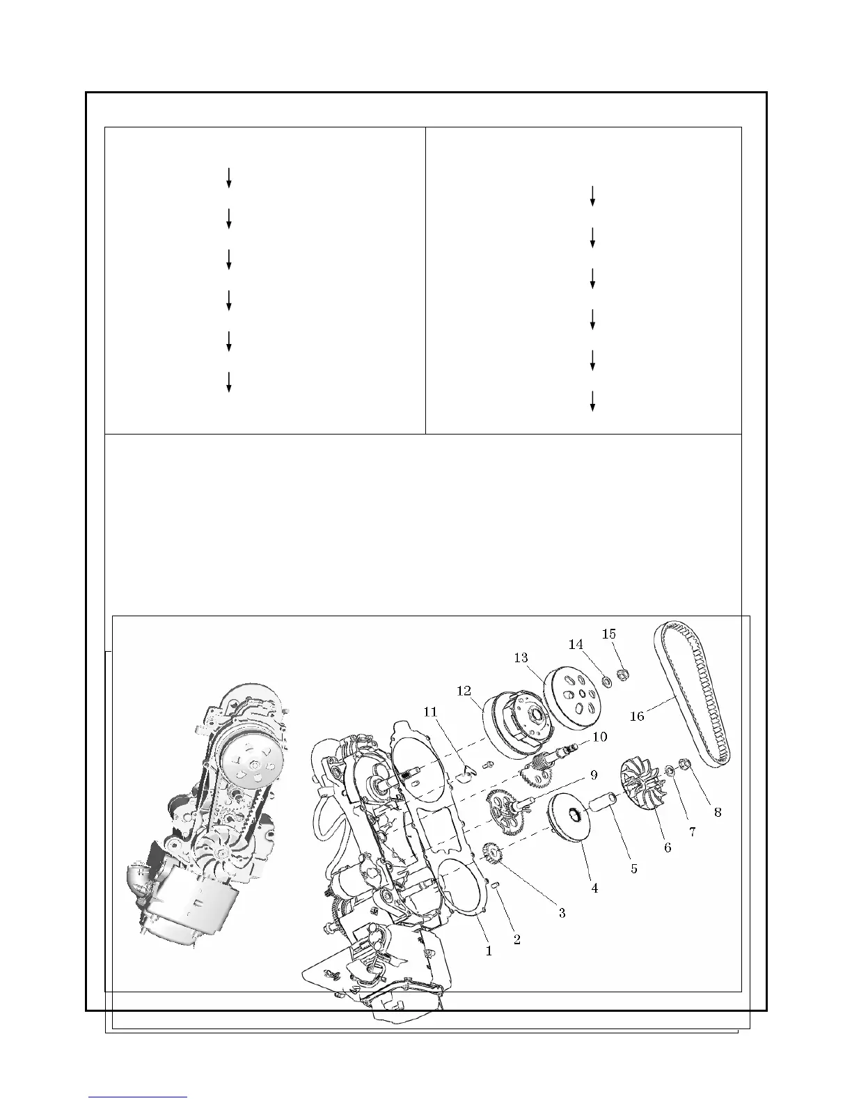
INSTALLATION
Starting transition gear assy.(7)/kicing starter
sprocket assy.(8)
Starting spring slice(9)
Starting driven gear (1)
Driveng wheel assy.(2)/bush(3)
Driving impeller(4)/ gasket(5)/ nut(6)
strap(14)/driven disc assy.(10)
acentric disc(11)/gasket(12)/nut(13)
Notice:
::
:
1、 When installing start transition gear wheel and kicing start gear assy., daub axes end with little butter; keep arrow mark
on transition gear dead against crankshaft, lineation on kicking start gear dead against rushing point on transition gear;
carefully pull kicking start shaft spring to correct position with some tool, be careful that spring doesn’t turn back;
position starting spring slice correctly and lock bolt, and the torque is 10~12N•M.
2、 When installing strap, anticlockwise place strap into groove of driven wheel strap, then cover driving impeller groove
with strap and install driven wheel assy. into input axes, and then assemble acentric disc, dish gasket and nut.
3、 Finally, lock nut (15)and nut(8),the torque is 45~55N•M,then drive strp, now driven wheel strap disc releases freely.
 Loading...