3-6 Configuring TCP/IP addresses Model 2701 Instrument Networking Instruction Manual
4. Select the fourth byte (Node identifier). Use an easily recognizable pattern if assigning
numbers to many nodes (see
Figure 3-1).
5. Select the Subnet mask for the network class (see Table 3-2).
6. Set the Model 2701 address(es) as required. (See “Changing Model 2701 TCP/IP
addresses” on page 3-7.
NOTE Since the network scheme in Figure 3-1 does not connect to a corporate LAN, the
gateway address selected does not matter (it can be set to 0.0.0.0).
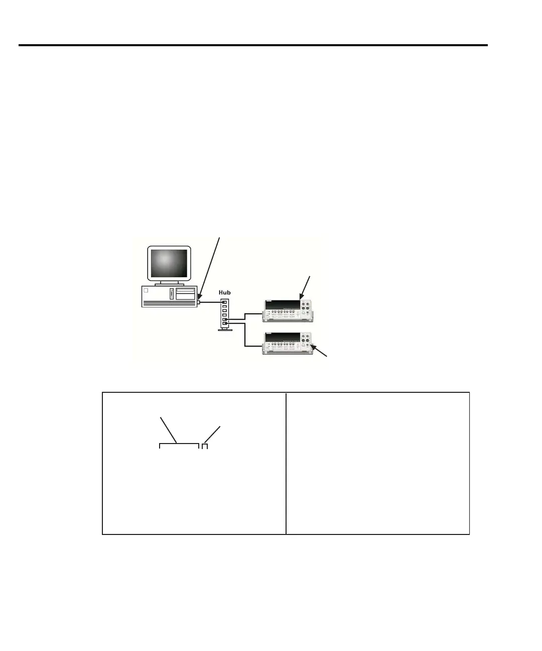
Figure 3-1
IP address byte location sample
Subnet mask: 255.255.255.0
Subnet mask: 255.255.255.0
• Network ID: Must be the same for
all nodes on the network that are
communicating with each other.
• Node designation: Must be different
from each node on the network but
within the parameters of the networks
class and subnet mask.
Subnet mask: Must be the same for
all nodes on the network that are
communicating.
IP Address: Made up of two parts:
IP Address: 192.168.0.2
Subnet mask: 255.255.255.0
IP Address: 192.168.0.3
IP Address: 192.168.0.50
Subnet mask: 255.255.255.0
IP Address: 192.168.0.2
Network ID
Node designation

 Loading...


