APPLICATIONS
PROBE
ADJUSTMENT
To obtain an accurate measurement result, the probe must
be adjusted correctly before measurement.
1.
Connect the probe to the INPUT terminal and set the
control for a normal sweep display.
2.
Connect the probe to the CAL terminal on the
front
panel,
and adjust the
SWEEP
TIME/DIV switch so
that
several
cycles
of this signal are displayed.
3.
Adjust the trimmer on the probe to obtain the following
correct
compensation waveform.
Correct
compensation
Over
compensation
Insufficient
compensation
Fig.
15
2.
Set the A TRIG
MODE
to AUTO and AC-GND-DC to the
GND position, which established the zero volt reference.
Using
the • POSITION control, adjust the trace position
to the desired reference level position, making sure not
to disturb this setting once made.
3.
Set the AC-GND-DC switch to the DC position to
observe
the input waveform, including its DC compo-
nent. If an appropriate reference level or VOLTS/DIV
setting was not made, the waveform may not be visible
on the CRT
screen
at this point. If so, reset VOLTS/DIV
and/or the
%
POSITION control.
4. Use the o POSITION control to bring the portion of
the waveform to be measured to the center vertical
graduation line of the CRT
screen.
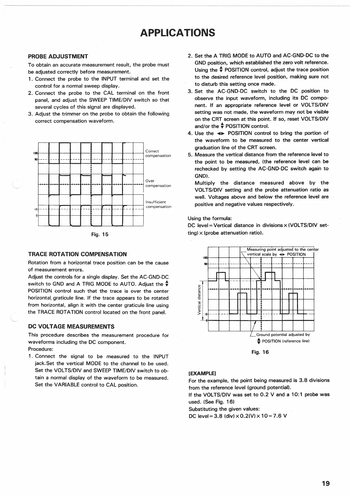
5. Measure the vertical distance
from
the reference level to
the point to be measured, (the reference level can be
rechecked
by setting the AC-GND-DC switch again to
GND).
Multiply
the distance measured above by the
VOLTS/DIV
setting and the probe attenuation ratio as
well.
Voltages above and below the reference level are
positive and negative values respectively.
Using
the formula:
DC
level - Vertical distance in
divisions
x (VOLTS/DIV
set-
ting)
x (probe attenuation ratio).
TRACE ROTATION COMPENSATION
Rotation
from
a horizontal trace position can be the
cause
of measurement errors.
Adjust
the controls for a single display. Set the AC-GND-DC
switch
to GND and A TRIG MODE to AUTO. Adjust the %
POSITION control
such
that
the trace is over the center
horizontal, graticule line. If the trace appears to be rotated
from
horizontal, align it
with
the center graticule line using
the
TRACE
ROTATION control located on the
front
panel.
DC VOLTAGE MEASUREMENTS
This
procedure describes the measurement procedure for
waveforms including the DC component.
Procedure:
1.
Connect the signal to be measured to the INPUT
jack.Set
the vertical MODE to the channel to be
used.
Set
the VOLTS/DIV and
SWEEP
TIME/DIV switch to ob-
tain a normal display of the waveform to be measured.
Set
the
VARIABLE
control to CAL position.
[EXAMPLE]
For
the example, the point being measured is 3.8 divisions
from
the reference level (ground potential).
If the VOLTS/DIV was set to 0.2 V and a 10:1 probe was
used.
(See Fig. 16)
Substituting the given values:
DC
level = 3.8 (div) x
0.2(V)
x 10 = 7.6 V
19
Measuring
point
adjusted
to
the center
vertical
scale
by o
POSITION
.Ground
potential adjusted
by
Y
POSITION (reference line)
Fig.
16
Vertical
distance

 Loading...


