TRIPLE-TRACE
APPLICATIONS
The
sensitivities of channel 1 thru channel 3 are calibrated
and each channel has 60 MHz band width. (For CS-1045,
40 MHz) The trigger signal of channel 3 can be obtained
from
its preamplifier.
This
unit can be used not only for external synchronization
but also for checking triple-trace at a time.
Application
1:
Checking logic signal timing.
2.
Monitoring
video
signals.
3.
Measuring audio signal gain and phase
characteristics.
The
details of the logic signal timing checking are described
below.
Logic
signal timing indication
Control setting
Vertical MODE: TRI
HORIZ MODE: A
SOURCE:
CHS
To
obtain stable synchronization, synchronize
with
the
longest
period channel (in this
case,
CH3).
Main
sweep
Delayed
sweep
OBSERVATION OF THE START PORTION OF THE
IRREGULAR WAVEFORM
To
observe the start portion of the irregular waveform,
magnification of the start portion of the waveform can be
made
with
the
DELAY
TIME
ZERO.
Procedure;
1.
Apply the signal to INPUT jack and set the vertical
MODE to the channel to be used and adjusting the
various
controls for a normal display.
2.
Use the A
SWEEP
TIME/DIV and HOLDOFF controls to
adjust
the display
such
that
a number of
cycles
of
waveform is observed.
Next,
set the B TRIG MODE to
DELAY
= 0.
3.
Set the HORIZ MODE to ALT or B and use the •
POSI-
TION and
TRACE
SEPARATION controls to adjust the
display
such
that
the display is easily observed.
4. The observation of the start portion of the waveform
can
be made to set the B
SWEEP
TIME/DIV to as fast a
setting as possible consistent
with
observation.
For
time
measurement, calculate
from
the B
SWEEP
TIME/DIV setting.
Fig.
39
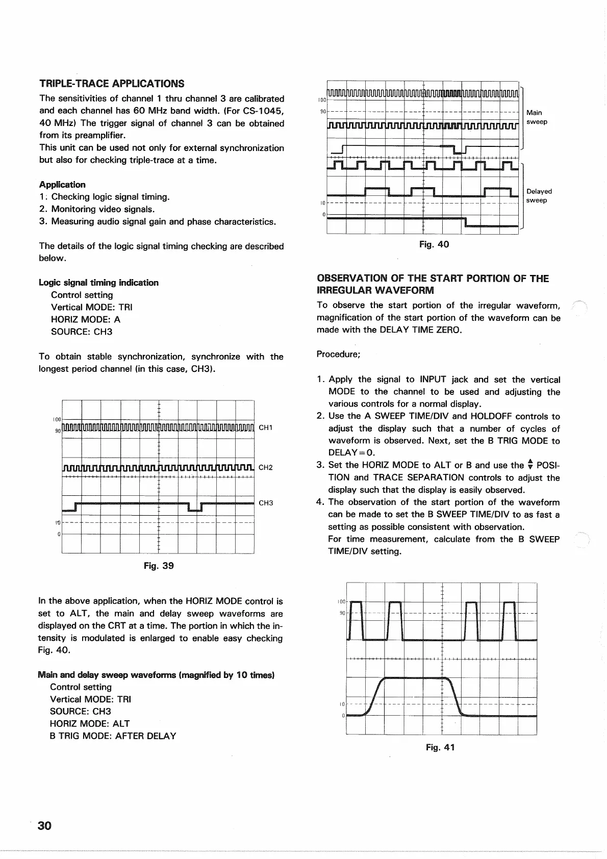
In the above application, when the HORIZ MODE control is
set
to ALT, the main and delay sweep waveforms are
displayed
on the CRT at a time. The portion in which the in-
tensity is modulated is enlarged to enable
easy
checking
Fig.
40.
Main
and delay sweep waveforms (magnified by 10 times)
Control setting
Vertical MODE: TRI
SOURCE:
CH3
HORIZ MODE: ALT
B
TRIG MODE:
AFTER
DELAY
Fig.
41
30
Fig.
40

 Loading...


