2.
Count the number of
cycles
of waveform between a
chosen
set of vertical graduation lines.
Using
the horizontal distance between the vertical lines
used
above and the
SWEEP
TIME/DIV, the
time
span
may
be calculated.
Multiply
the reciprocal of this value
by the number of
cycles
present in the given
time
span.
If "x 10 MAG" is used multiply this further by 10.
Note
that
errors will occur for displays having only a few
cycles.
Using
the formula:
# of
cycles
x " x 10 MAG" value
Freq=
Horizontal distance (div) x
SWEEP
TIME/DIV setting
Count
cycles
between
this
portion
[EXAMPLE]
For
the example, within 7 divisions there are 10
cycles.
The
SWEEP
TIME/DIV is 5 jis. (See Fig. 21)
Substituting the given value:
Freq= —
=285.7
kHz
7 (div) x 5 {(is)
PULSE WIDTH MEASUREMENTS
Procedure:
1.
Apply the pulse signal to the INPUT jack. Set the vertical
MODE to the channel to be
used.
2.
Use the VOLTS/DIV, VARIABLE and w POSITION to ad-
just
the waveform
such
that
the pulse is easily observed
and
such
that
the center pulse
width
coincides
with
the
center horizontal line on the CRT
screen.
3.
Measure the distance between the intersection of the
pulse
waveform and the center horizontal line in divi-
sions.
Be sure
that
the VARIABLE control is in the CAL.
Multiply
this distance by the
SWEEP
TIME/DIV and by
1/10 is "x 10 MAG" mode is being
used.
Using
the formula:
Pulse
width
= Horizontal distance (div) x
(SWEEP
TIME/DIV
setting) x " x MAG 10"value"
1
(1/10)
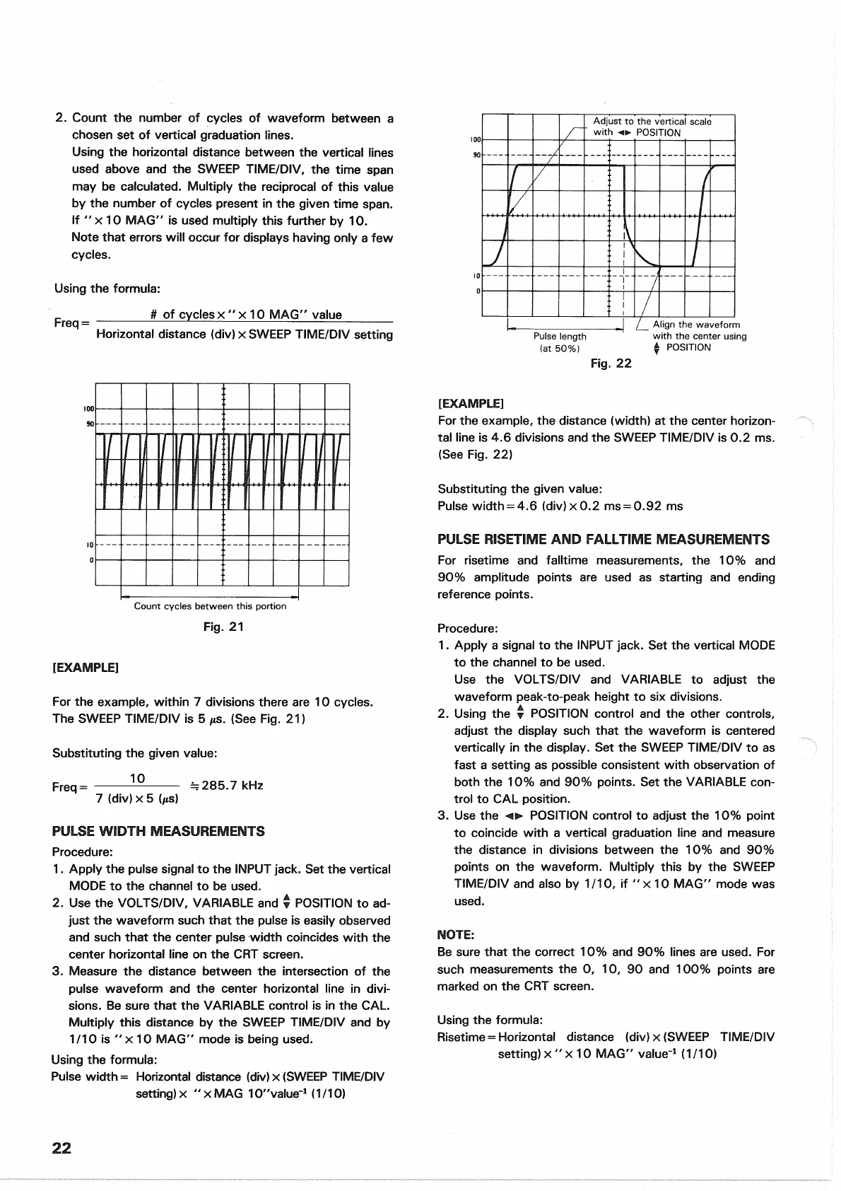
Adjust
to
the
vertical
scale
with
POSITION
[EXAMPLE]
For
the example, the distance
(width)
at the center horizon-
tal line is 4.6 divisions and the
SWEEP
TIME/DIV is 0.2 ms.
(See
Fig. 22)
Substituting the given value:
Pulse
width
= 4.6 (div) x 0.2 ms = 0.92 ms
PULSE RISETIME AND FALLTIME MEASUREMENTS
For
risetime and
falltime
measurements, the 10% and
90% amplitude points are used as starting and ending
reference points.
Procedure:
1.
Apply a signal to the INPUT jack. Set the vertical MODE
to the channel to be
used.
Use
the VOLTS/DIV and VARIABLE to adjust the
waveform peak-to-peak height to six divisions.
2.
Using the • POSITION control and the other controls,
adjust
the display
such
that
the waveform is centered
vertically in the display. Set the
SWEEP
TIME/DIV to as
fast a setting as possible consistent
with
observation of
both the 10% and 90% points. Set the
VARIABLE
con-
trol
to CAL position.
3.
Use the POSITION control to adjust the 10% point
to coincide
with
a vertical graduation line and measure
the distance in divisions between the 10% and 90%
points on the waveform.
Multiply
this by the
SWEEP
TIME/DIV and also by 1/10, if "x 10 MAG" mode was
used.
NOTE:
Be
sure
that
the correct 10% and 90% lines are
used.
For
such
measurements the 0, 10, 90 and 100% points are
marked on the CRT
screen.
Using
the formula:
Risetime
= Horizontal distance (div) x
(SWEEP
TIME/DIV
setting) x " x 10 MAG" value"
1
(1/10)
22
Pulse
length
(at
50%)
Align the waveform
with
the
center
using
*
POSITION
Fig.
22
Fig.
21

 Loading...


