CONTROLS
AND INDICATORS
FRONT
PANEL
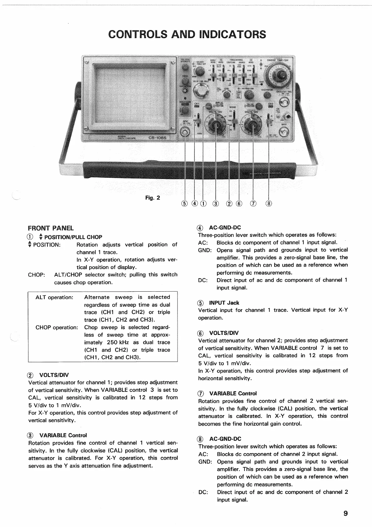
(D • POSITION/PULL CHOP
• POSITION: Rotation adjusts vertical position of
channel
1 trace.
In X-Y operation,
rotation
adjusts ver-
tical position of display.
CHOP:
ALT/CHOP selector switch; pulling this switch
causes
chop operation.
ALT
operation: Alternate sweep is selected
regardless
of sweep
time
as dual
trace (CH1 and CH2) or
triple
trace (CH1, CH2 and CH3).
CHOP
operation: Chop sweep is selected regard-
less
of sweep
time
at approx-
imately 250 kHz as dual trace
(CH1 and CH2) or
triple
trace
(CH1,
CH2 and CH3).
(2) VOLTS/DIV
Vertical attenuator for channel 1; provides step adjustment
of vertical sensitivity. When
VARIABLE
control 3 is set to
CAL,
vertical sensitivity is calibrated in 12 steps
from
5
V/div to 1 mV/div.
For
X-Y operation, this control provides step adjustment of
vertical sensitivity.
(D
VARIABLE Control
Rotation provides
fine
control of channel 1 vertical
sen-
sitivity. In the
fully
clockwise (CAL) position, the vertical
attenuator is calibrated. For X-Y operation, this control
serves
as the Y axis attenuation
fine
adjustment.
(4) AC-GND-DC
Three-position lever switch which operates as follows:
AC:
Blocks dc component of channel 1 input signal.
GND: Opens signal path and grounds input to vertical
amplifier. This provides a zero-signal base line, the
position of which can be used as a reference when
performing dc measurements.
DC:
Direct input of ac and dc component of channel 1
input signal.
(5) INPUT
Jack
Vertical input for channel 1 trace. Vertical input for X-Y
operation.
(6)
VOLTS/DIV
Vertical attenuator for channel 2; provides step adjustment
of vertical sensitivity. When VARIABLE control 7 is set to
CAL,
vertical sensitivity is calibrated in 12 steps
from
5
V/div to 1 mV/div.
In X-Y operation, this control provides step adjustment of
horizontal sensitivity.
(7) VARIABLE Control
Rotation provides
fine
control of channel 2 vertical
sen-
sitivity. In the
fully
clockwise (CAL) position, the vertical
attenuator is calibrated. In X-Y operation, this control
becomes
the
fine
horizontal gain control.
(J)
AC-GND-DC
Three-position lever switch which operates as follows:
AC:
Blocks dc component of channel 2 input signal.
GND: Opens signal path and grounds input to vertical
amplifier. This provides a zero-signal base line, the
position of which can be used as a reference when
performing dc measurements.
DC:
Direct input of ac and dc component of channel 2
input signal.
9
Fig.
2

 Loading...


