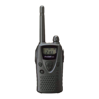
TK-3170/3173
4
5-2. Connection Procedure
1. Connect the transceiver to the personal computer with
the interface cable.
2. When the POWER switch on, user mode can be entered
immediately. When PC sends command the transceiver
enter PC mode, and “PROGRAM” is displayed on the
LCD.
When data transmitting from transceiver, the red LED is
lights.
When data receiving to transceiver, the green LED is
lights.
Note:
The data stored in the personal computer must match
model type, when it is written into the flash memory.
5-3. KPG-22 Description
(PC programming interface cable: Option)
The KPG-22 is required to interface the transceiver to the
computer. It has a circuit in its D-subconnector (25-pin) case
that converts the RS-232C logic level to the TTL level.
The KPG-22 connects the SP/MIC connector of the trans-
ceiver to the computers RS-232C serial port.
5-4. Programming Software KPG-101D Description
The KPG-101D is the programming software for the trans-
ceiver supplied on a CD-ROM. This software runs under MS-
Windows 98, ME, Windows 2000 or XP on an IBM-PC or
compatible machine.
The data can be input to or read from the transceiver and
edited on the screen. The programmed or edited data can be
printed out. It is also possible to tune the transceiver.
6. Firmware Programming Mode
6-1. Preface
Flash memory is mounted on the transceiver. This allows
the transceiver to be upgraded when new features are re-
leased in the future. (For details on how to obtain the firm-
ware, contact Customer Service.)
6-2. Connection Procedure
Connect the transceiver to the personal computer (IBM
PC or compatible) with the interface cable (KPG-22). (Con-
nection is the same as in the PC Mode.)
6-3. Programming
1. Start up the firmware programming software (Fpro.exe).
2. Set the communications speed (normally, 115200 bps)
and communications port in the configuration item.
3. Set the firmware to be updated by File name item.
4. Turn the transceiver power ON with the [Side2] key held
down. Then, the orange LED on the transceiver lights and
“PROG 1152” is displayed.
5. Check the connection between the transceiver and the
personal computer, and make sure that the transceiver is
in the Program mode.
6. Press write button in the window. When the transceiver
starts to receive data, the “LOADING” is displayed.
7. If writing ends successfully, the checksum is calculated
and a result is displayed.
8. If you want to continue programming other transceivers,
repeat steps 4 to 7.
Note:
This mode cannot be entered if the Firmware Program-
ming mode is set to Disable in the Programming software.
6-4. Function
1. If you press the [Side2] key while “PROG 1152” is dis-
played, the display changes to “PROG 192” to indicate
that the write speed is low speed (19200 bps). If you
press the [Side2] key again while “PROG 192” is dis-
played, the display changes to “PROG 384”. If you press
the [Side2] key again while “PROG 384” is displayed, the
display changes to “PROG 576”. If you press the [Side2]
key again while “PROG 576” is displayed, the display re-
turns to “PROG 1152”.
2. If you press the [Side1] key while “PROG 1152” is dis-
played, the checksum is calculated, and a result is dis-
played. If you press the [Side1] key again while the
checksum is displayed, “PROG 1152” is redisplayed.
Note:
Normally, write in the high-speed mode.
7. Clone Mode
Programming data can be transferred from one trans-
ceiver to another by connecting them via their SP/MIC con-
nectors. The operation is as follows (the transmit transceiver
is the master and the receive transceiver is a slave).
The following data cannot be cloned.
• Tuning data
• Embedded message with password
• Serial number
The “password” of description by explanation of 1. to 7.
are “Read Authorization Password”.
1. Turn the master transceiver power ON with the [B] key
held down. If the Data password is set to the transceiver,
the transceiver displays “CLN LOCK”. If the password is
not set, the transceiver displays “CLONE”.
2. When you enter the correct password, and “CLONE” is
displayed, the transceiver can be used as the cloning mas-
ter. The following describes how to enter the password.
3. How to enter the password with the keypad;
If you press a key while “CLN LOCK” is displayed, the
number that was pressed is displayed on the transceiver.
Each press of the key shifts the display in order to the left.
When you enter the password and press the [
*
] or [S] key,
“CLONE” is displayed if the entered password is correct.
If the password is incorrect, “CLN LOCK” is redisplayed.
REALIGNMENT
 Loading...

