28
Circuit Block Diagram
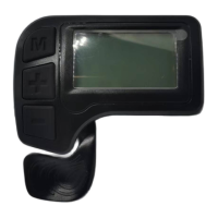
Table 1 : Standard connector cable sequence (display without
throttle)
Standard
sequence
Wire color Definition
1
red(VCC)
Power+
2 blue(K) Power of controller
3 black(GND) GND
4 green(RX) Receiving data
5 yellow(TX) Transmitting data
Notes: some displays are with waterproof cables, wires hidden
inside the wire cover.
Table 2: Standard connector cable sequence (display with throttle)
Standard
sequence
Wire color Definition
1
red(VCC)
Power+
2 blue(K) Power of controller
3 black(GND)) Gnd
4 green(RX) Receiving data
5 yellow(TX) Transmitting data
6 white(ZB) Throttle signal data

 Loading...