7-4 CK25/30/35
AUXILIARY HYDRAULICS
JOYSTICK VALVE
To begin test operation, slightly move
the control lever from the "N" position.
Slowly raise the loader boom just
enough for the bucket to clear the
ground when fully dumped. Slowly
work through the dump and roll back
cycles.
TWO STAGE VALVE TYPE
This loader control valve has two stage
dump position. The first dump position
by moving the lever to the right is the
"Regular" dump position.
It has good power and control for dump-
ing precisely. This position should be
used when operating another implement
with the loader's control valve.
The second dump position (to further
right) features greater speed for
dumping. These two position are sepa-
rated by a "Feel" position for your
convenience.
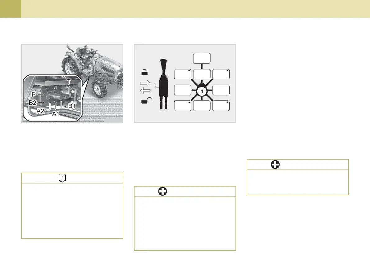
(T) To the Tank (P) From the Pump
(A1) A1 PORT (A2) A2 PORT
(B1) B1 PORT (B2) B2 PORT
z Boom Cylinder : A1,B1
z Bucket Cylinder : A2,B2
704O707C704O706C
zz
zz
z When the lever is at each corner
position marked by*, boom and
bucket cylinders work at the same
time. However, the position marked
by cross is not recommended for
scooping because of insufficient lift
force.
NOTE
zz
zz
z Do not move the control lever
into float position when the
bucket is off the ground.
IMPORTANT
zz
zz
z If the boom or bucket does not
work in the directions indicated
in the label, lower the bucket
to the ground, stop the engine,
and relieve all hydraulic
pressure. Recheck and correct
all hydraulic connections.
IMPORTANT
FLOAT
DOWN
DOWN
& ROLL
BACK
UP
ROLL
BACK
UP
& ROLL
BACK
DUMP
DUMP
&
DOWN
UP
&
DOWN
 Loading...