KP310V1.0 Controller Operation Manual
- 14 -
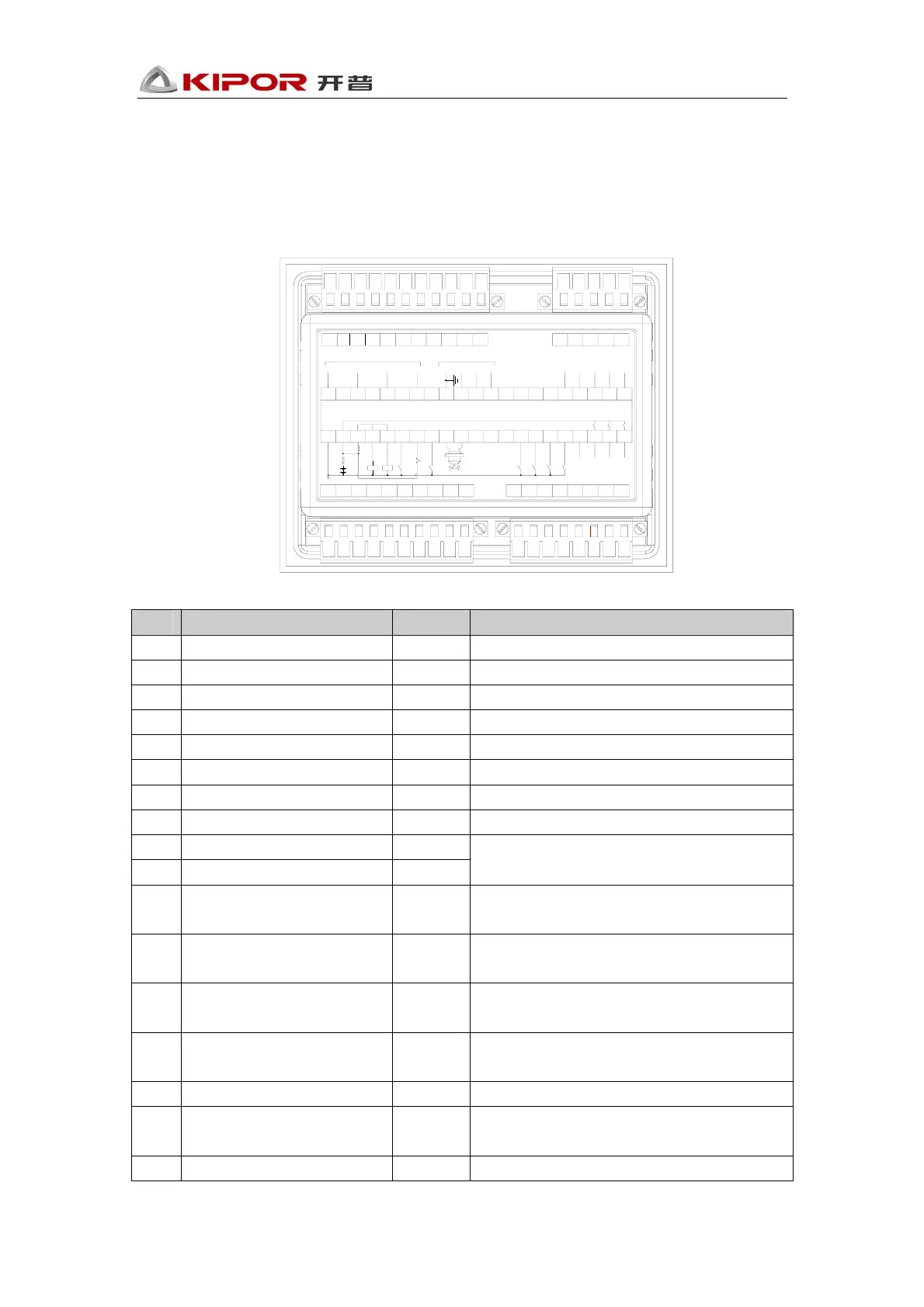
7. Wiring
The back panel of KP310V1.0 controller is as follows:
31 30 29 28 27 26 25 23 22 21 20 1924
1 2 3 4 5 6 7 8 9 10 11 12 13 14 15 16 17 18
12
3
4
56
7
8910
11 12
13
14
15 16
17
18
1921 2022232425262728293031
KP310V1.0 GENSET CONTROLLER
ABCN
Genset Voltage
IA IB ICICOM
Current
(Rated 5mA)
DIR
TXD
RXD
Comm_GND
Comm_VCC
B-
B+
EM Stop
+
Fuel
High Temp
Oil Press
Aux_In1
Aux_In2
Remote
120/240 Select
Crank
Start sw
Bat Charge
Preheat
Aux_Out1
Aux_Out2
+
-
MPU
Description of wiring terminals:
No. Function Diameter Note
1 DC Working power input:B- 1.0mm
2
Connect with the battery cathode
2 DC Working power input:B+ 1.0mm
2
Connect with the battery anode
3 Emergency stop input 1.0mm
2
Connect with B+ with emergency stop button
4 Fuel relay output 1.0mm
2
Rated current:15A, provide B+ by port 3
5 Start relay output 1.0mm
2
Rated current:15A, provide B+ by port 3
6 Dual voltage selection input 1.0mm
2
Active if lower voltage circuit is closed
7 Ignition lock start input 1.0mm
2
Connect to the ignition lock start terminal
8 Remote control input 1.0mm
2
Remote input terminal, low voltage active
9 Revolution sensor input + 1.0mm
2
10 Revolution sensor input - 1.0mm
2
Recommend to connect the revolution sensor
with shielding wire
11
Water temperature switch
input
1.0mm
2
Connect with water temperature sensor
12 Oil pressure switch input 1.0mm
2
Connect with oil pressure sensor 连接机油压
力传感器
13
Programmable configuration
input 1
1.0mm
2
Provide B+ by port 2
14
Programmable configuration
input 2
1.0mm
2
Provide B+ by port 2
15 Charging voltage detect 1.0mm
2
Connect with generator D+ terminal
16 Preheat relay output 1.0mm
2
Normal open output, rated current:1A, provide
B+ by port 2
17 Programmable relay output 1 1.0mm
2
Normal open output, rated current:1A
 Loading...