TP-6805 8/1524 Section 2 Scheduled Maintenance
2.2.6 Oil Coo ler, 20RESA/RESAL/RESB
The oil cooler is used on models 20RESA, 20RESAL,
and 20RESB.
Inspect and clean the oil cooler at the intervals indicated
in the service schedule. The oil cooler must be kept free
of debris.
Remove the front enclosure panel to access the oil
cooler. See Section 7.2 for instructions to remove the
front panel.
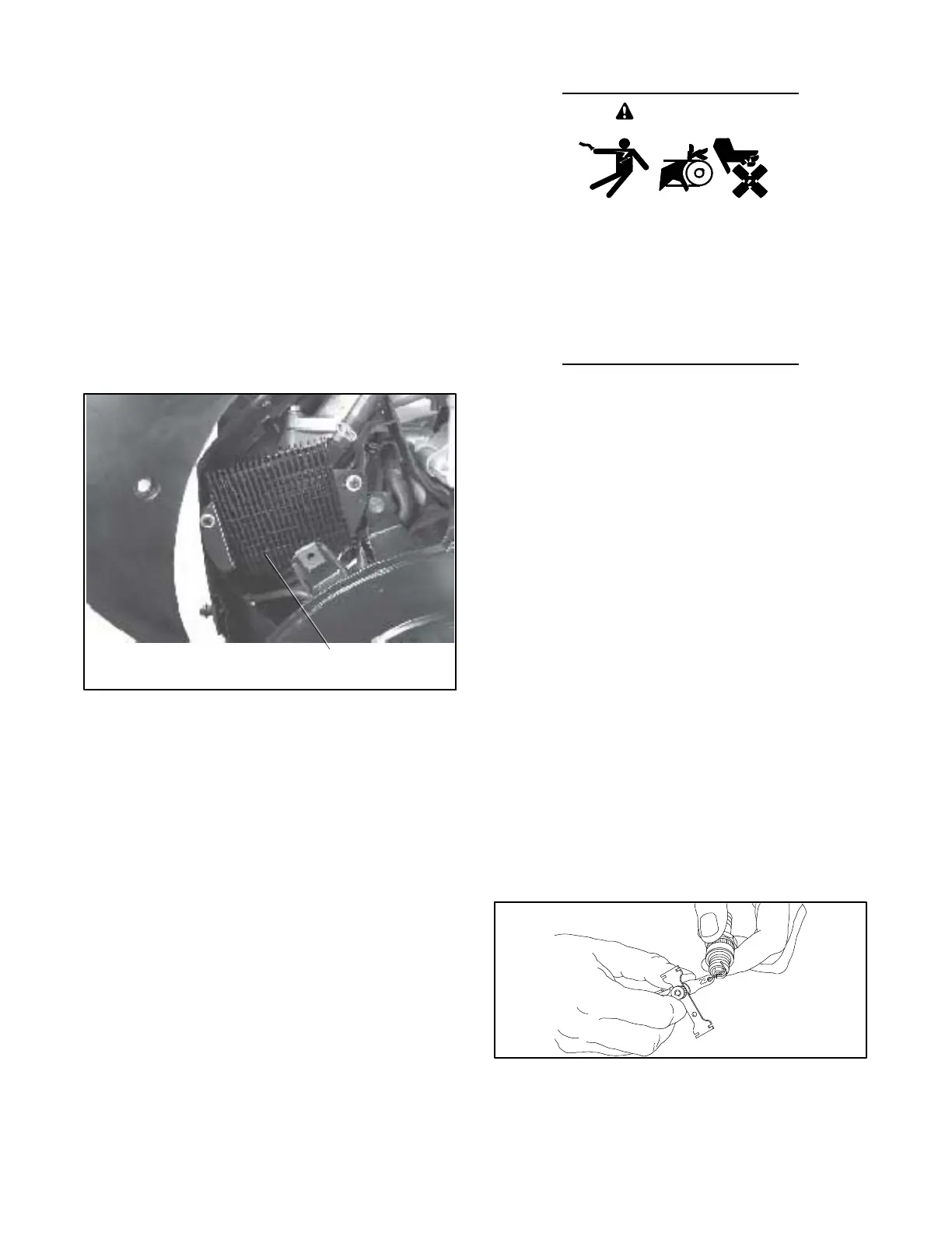
See Figure 2-6 for the oil cooler location. The oil cooler
is located under the No. 2 cylinder shroud. Remove the
top mounting screw and loosen the two side screws,
then lift off the cylinder shroud. Clean the outside of the
oil cooler fins with a brush or with compressed air.
1
62 590 01
1. Oil cooler
Figure 2-6 Oil Cooler, 20 kW Models
2.3 Resetting the Maintenance
Reminder
The RDC2 controller displays maintenance reminder
messages when it is time to change the oil and perform
other routine maintenance. After changing the oil and
performing other maintenance items shown in the
maintenance schedule in Section 2.1, reset the
maintenance reminder on the controller.
1. In the Overview menu, step down to the Next
Maintenance screen.
2. Press the Select button.
3. Press the Up arrow button so that “Reset Maint
Timer? Yes” is displayed.
4. Press the Select button. The next maintenance
interval and date will be displayed.
2.4 Spark Plugs
Accidental starting.
Can cause severe injury or death.
Disconnect the battery cables before
working on the generator set.
Remove the negative (--) lead first
when disconnecting the battery.
Reconnect the negative (--) lead last
when reconnecting the battery.
WARNING
Disabling the generator set. Accidental starting can
cause severe injury or death. Before working on the
generator set or equipment connected to the set, disable the
generator set as follows: (1) Press the generator set off/reset
button to shut down the generator set. (2) Disconnect the
power to the battery charger, if equipped. (3) Remove the
battery cables, negative (--) lead first. Reconnect the negative
(--) lead last when reconnecting the battery. Follow these
precautions to prevent the starting of the generator set by the
remote start/stop switch.
Reset the spark plug gap or replace the plugs with new
plugs as necessary.
1. Clean the area around the base of the spark plug to
keep dirt and debris out of the engine.
2. Remove the spark plug and check its condition.
Replace the spark plug if it is worn or if its reuse is
questionable.
3. Check the spark plug gap using a wire feeler
gauge. Adjust the gap to 0.76 mm (0.030 in.) by
carefully bending the ground electrode. See
Figure 2-7 and Figure 2-8.
4. Reinstall the spark plug into the cylinder head.
Torque the spark plug to 24.4--29.8 Nm
(18--22 ft. lb.).
1--514
Figure 2-7 Checking the Spark Plug Gap
 Loading...


