TP-6805 8/15 37Section 4 Controller
Section 4 Controller
4.1 Introduction
The RDC2 and DC2 controllers manage the operation of
the generator set, a Model RXT transfer switch (if
equipped), the optional Programmable Interface
Module (PIM), and optional load management device.
See the generator set Operation Manual for controller
operation instructions.
This section covers adjustment and replacement of the
RDC2 and DC2 controllers. See Section 5.14 for
troubleshooting information.
4.2 Controllers
Model RESA/B/C/D generator sets are equipped with
the RDC2 controller. RESAL/RESCL models have the
DC2 controller. Revised RDC2 and DC2 controllers
were introduced in 2014. Operation and setup of the
revised controllers are the same as the original.
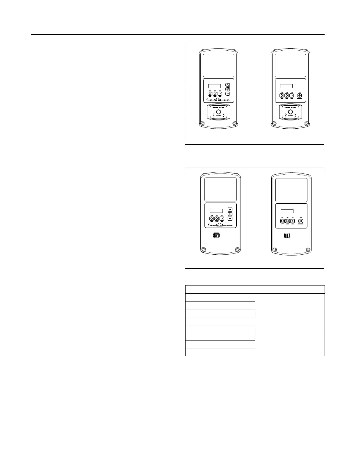
The original controller can be identified as follows:
D The USB port and mini circuit breaker are located
behind a cover with a thumbscrew.
D The circuit board, visible on the back of the controller,
is green.
The original RDC2 and DC2 controllers are shown in
Figure 4-1.
Revised controllers can be identified as follows:
D The USB port is located behind a small rubber cover.
D The mini circuit breaker is located near, but not on, the
controller. See Section 5.4.
D The circuit board, visible on the back of the controller,
is red.
Revised controllers are shown in Figure 4-2.
See the service view for the controller location on the
generator set.
RDC2 DC2
Figure 4-1 RDC2 and DC2 Original Controllers
(green board)
RDC2 DC2
Figure 4-2 Revised Controllers (red board)
Generator Set Model Controller
14RESA
RDC2
20RESA
20RESB
20RESC
20RESD
14RESAL
DC2
20RESAL
20RESCL
Figure 4-3 Controllers, by Model
 Loading...


