TP-6805 8/1598 Section 6 Component Testing and Adjustment
6.4 Main Field (Rotor)
The two-pole rotor creates the magnetic field needed to
produce alternating current in the stator windings.
Before testing, inspect the rotor for visible damage to
pole shoes, insulation, exposed coil windings, and slip
ring surfaces. Rotate the bearing to check for wear, heat
discoloration, or noise.
Accidental starting.
Can cause severe injury or death.
Disconnect the battery cables before
working on the generator set.
Remove the negative (--) lead first
when disconnecting the battery.
Reconnect the negative (--) lead last
when reconnecting the battery.
WARNING
Disabling the generator set. Accidental starting can
cause severe injury or death. Before working on the
generator set or equipment connected to the set, disable the
generator set as follows: (1) Press the generator set off/reset
button to shut down the generator set. (2) Disconnect the
power to the battery charger, if equipped. (3) Remove the
battery cables, negative (--) lead first. Reconnect the negative
(--) lead last when reconnecting the battery. Follow these
precautions to prevent the starting of the generator set by the
remote start/stop switch.
High voltage test. Hazardous voltage can cause severe
injury or death. Follow the instructions of the test equipment
manufacturer when performing high-voltage tests on the rotor
or stator. An improper test procedure can damage equipment
or lead to generator set failure.
Grounding electrical equipment. Hazardous voltage can
cause severe injury or death. Electrocution is possible
whenever electricity is present. Ensure you comply with all
applicable codes and standards. Electrically ground the
generator set, transfer switch, and related equipment and
electrical circuits. Turn off the main circuit breakers of all
power sources before servicing the equipment. Never contact
electrical leads or appliances when standing in water or on wet
ground because these conditions increase the risk of
electrocution.
Rotor Test Procedure
1. Press the OFF button on the controller to turn off
the generator set.
2. Disconnect utility power to the generator set.
3. Disconnect the generator set engine starting
battery, negative (--) lead first.
4. Check the rotor for continuity and resistance.
a. Raise and secure the b rushes away from the
slip rings by removing the two brush holder
mounting screws and moving the brush
assembly out of the way.
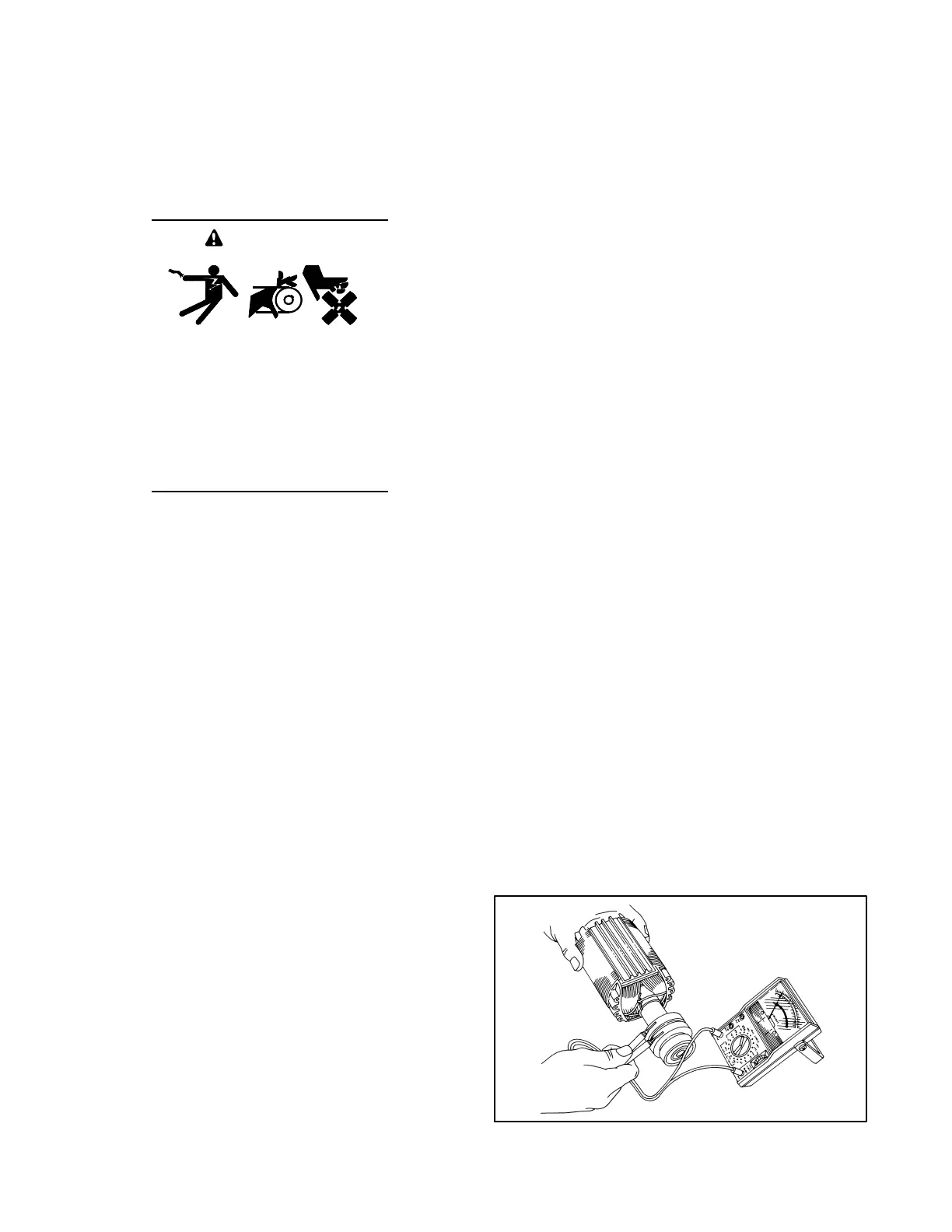
b. Measure the rotor resistance (ohms) between
the two slip rings; see Figure 6-9. See Section
1.6 for rotor resistance readings.
Note: Because ohmmeter accuracy varies,
resistance readings are approximate. Take
readings at room temperature.
c. If the resistance readings are low, perform a
megohmmeter test on rotor as described in the
next step.
5. Perform a megohmmeter test to determine
whether the rotor is shorted to ground.
a. Raise and secure the b rushes away from the
slip rings by removing the two brush holder
mounting screws and moving the brush
assembly out of the way.
b. Using a megohmmeter, apply 500 volts DC to
one rotor slip ring and the rotor poles or shaft.
Follow the instructions of the megohmmeter
manufacturer when performing this test.
Note: A reading of approximately 500 kOhms
(1/2 megohm) or higher indicates a
good rotor.
c. Repair or replace the rotor if the reading is less
than approximately 500 kOhms. A reading of
less than 500 kOhms indicates deterioration of
the winding insulation and possible current flow
to ground.
d. Following the test, remove the retainer wire
from the brush holder and check the brush
positions on the slip rings. See Section 6.6,
Brushes.
2-221
R13929-7
Figure 6-9 Rotor Resistance Check
 Loading...


