TP-6805 8/15 65Section 5 Troubleshooting
5.5 Circuit Protection
Line Circuit Breaker
The line circuit breaker interrupts the generator output in
the event of an overload condition or a fault in the wiring
between the generator and the load. If the circuit
breaker trips, reduce the load and check the wiring.
Auxiliary Winding Circuit Breaker
The mini-breaker in the controller’s service area
protects the alternators auxiliary winding. See
Figure 5-1 or Figure 5-2. If the breaker trips, check
connections 55, 66, FP, and FN to the alternator.
Controller Internal Circuit Protection
The controller is equipped with internal circuit protection
for accessory and main power overload conditions.
Press OFF to reset.
5.6 Emergency Stop Button
The generator set may be equipped with an optional
emergency stop button. See Figure 5-4 for the location.
If the emergency stop button is activated, the controller
display will show Emerg Stop Shutdwn.
1
ADV-8424
1. Emergency stop button location
NON-SERVICE SIDE VIEW
Figure 5-4 Emergency Stop Button (optional)
Emergency Stop Switch Operation
1. Push the red emergency stop button to stop the
generator set. The generator set shuts down
immediately and the controller displays Emerg
Stop Shutdwn.
2. To reset the generator set after an emergency stop:
a. Pull out the emergency stop button.
b. Open the enclosure roof to access the
generator set controller. Press the OFF button
on the controller to clear the shutdown
condition.
3. Press the AUTO button for automatic generator set
operation, if desired.
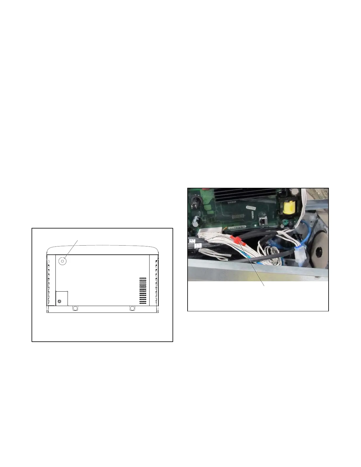
If the controller shows an emergency stop shutdown but
the button is not activated, check the ESS and ESN lead
connections to the emergency stop button assembly. If
there is no emergency stop button, connect ESS and
ESN securely together. See Figure 5-5.
1
1. Leads ESS and ESN in harness (controller mounting plate
removed for illustration only)
img0310
Figure 5-5 Emergency Stop Leads ESS and ESN
under the Controller
 Loading...


