TP-6805 8/1540 Section 4 Controller
management and cannot be changed by the user.
These outputs will display the load management relay
status.
Refer to Installation Instruction Sheet TT-1584,
provided with the PIM, for information about the input
and output events.
RBUS Devices
Up to four RBUS modules can be connected to the
generator set. RBUS modules can include one Model
RXT transfer switch, one programmable interface
module (PIM), one automatic paralleling module (APM),
and one load management device (load control module
(LCM), load shed kit, or the RXT combined
interface/load management board). If two generators
are paralleled using the APM, the second generator is
also considered an RBUS device but does not reduce
the number of RBUS modules that can be used.
Note: An RXT transfer switch with the combined
interface/load management board counts as two
RBUS devices (unless load management is
disabled on the combined board).
Load Management Devices
A load management device can be a load control
module (LCM), a load shed kit installed in an RDT or
RXT transfer switch, or a combined interface/load
management board installed in an RXT transfer switch.
Only one load management device can be connected.
The load management device counts as one RBUS
device.
A relay module (GM92001-KP1-QS) is a power relay
designed for use with the load shed kit or the combined
interface/load management board. The relay module
does not act as an RBUS device. See TT-1646.
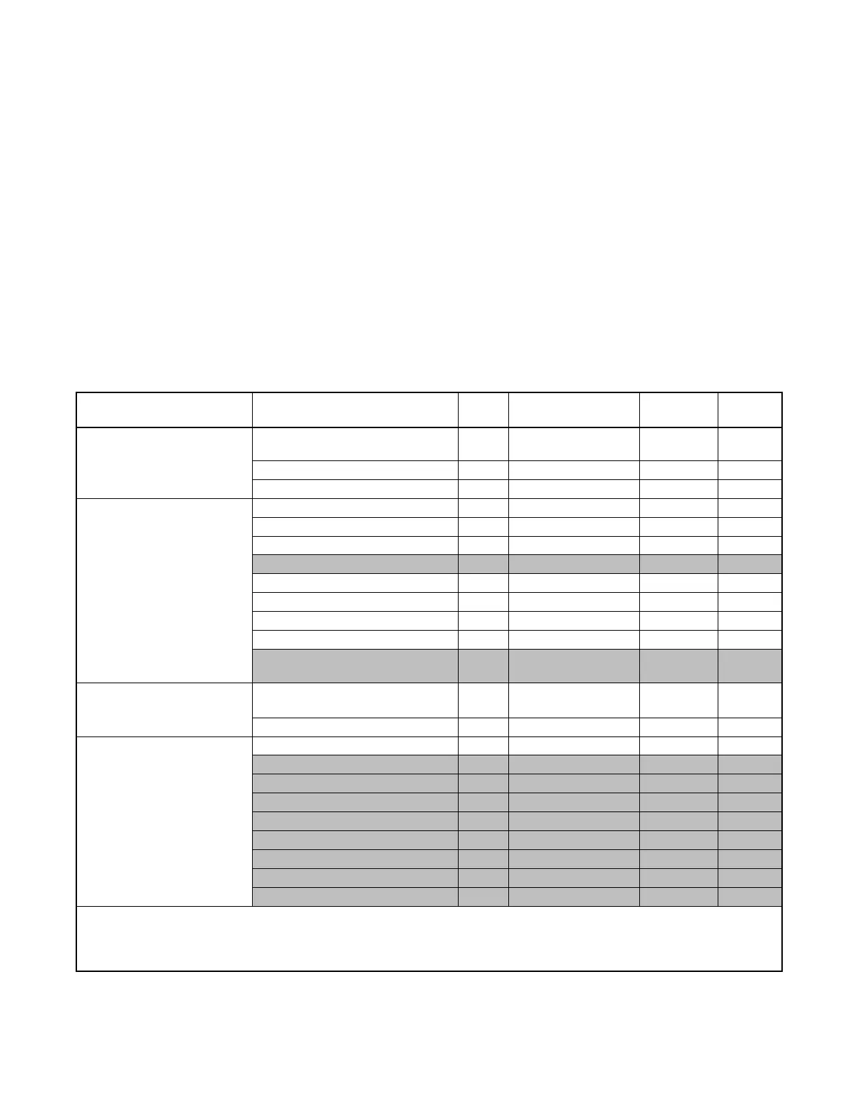
SiteTech Group Parameter Units
Adjustment
Range *
Default
Setting
Notes [
Identity
Vendor Read Only Kohler
Company
Product Read Only RDC 2
Firmware Version Read Only N/A
Engine Metering
Engine Speed R/min Read Only N/A
Engine Target Speed R/min Read Only N/A
Engine Oil Pressure kPa Read Only N/A
Engine Coolant Temperature _C Read Only N/A N/A
Battery Voltage V Read Only N/A
Lube Oil Temperature _C Read Only N/A
Genset Controller Temperature _C Read Only N/A
Engine Low Oil Pressure Switch Read Only N/A
Engine Compartment
Temperature
_C Read Only N/A N/A
Engine Speed Governor
Engine Speed Adjustment 0--99
See Section 4.4.2.
50
Engine Speed Gain Adjustment 35--65 50
Generator Metering
Generator Rotation Actual Read Only N/A 3-phase
Generator Current Lead/Lag L1 Read Only N/A N/A
Generator Current Lead/Lag L2 Read Only N/A N/A
Generator Current Lead/Lag L3 Read Only N/A 3-phase
Generator Current Total Lead/Lag Read Only N/A N/A
Generator Power Factor L1 Read Only N/A N/A
Generator Power Factor L2 Read Only N/A N/A
Generator Power Factor L3 Read Only N/A 3-phase
Generator Total Power Factor Read Only N/A N/A
* Read Only = Not adjustable
[ Notes indicate applicability to genset model and accessories. N/A = Not applicable to these generator s ets.
] See TT-1584 for more information about digital inputs and outputs.
w Load management device (LCM, load shed kit, or RXT with combined interface/ load management board)
 Loading...


