32 TP-6694 6/22
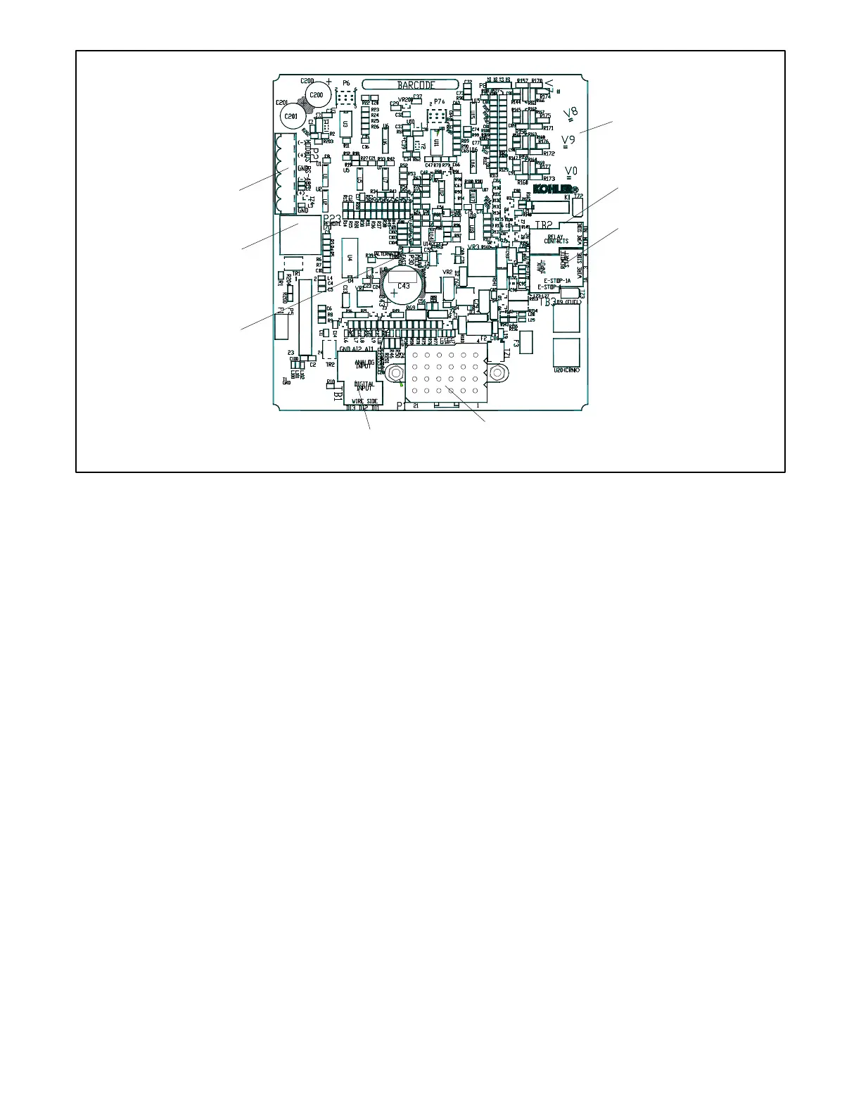
Figure 6 Main Circuit Board Connectors
P21 (6-Pin) Connector for (RS-485) connection of optional RSA or Modbus
®
communication.
P23 (8-Pin) Connector (RJ45) for optional input/output (I/O) module circuit board.
Refer to the section titled: Accessory Connections for specific connections of the following terminal block connections.
TB1 (6-Position) Terminal Block for analog and digital inputs.
TB2 (4-Position) Terminal Block for K1 relay outputs.
TB3 (6-Position) Terminal Block for E-stop, remote start contacts, and aux. input connections.
1.2.7 Terminal Jumper
A circuit board P30 jumper is set based on alternator type—Wound Field (300 kW and larger) or Fast Response
(less than 350 kW). The jumper is factory set and needs no further adjustment. See the figure titled: Main Circuit Board
Connectors for location of the P30 jumper.
Modbus
®
is a registered trademark of Schneider Electric.
 Loading...


