8.21
8
Section 8
Electrical System and Components
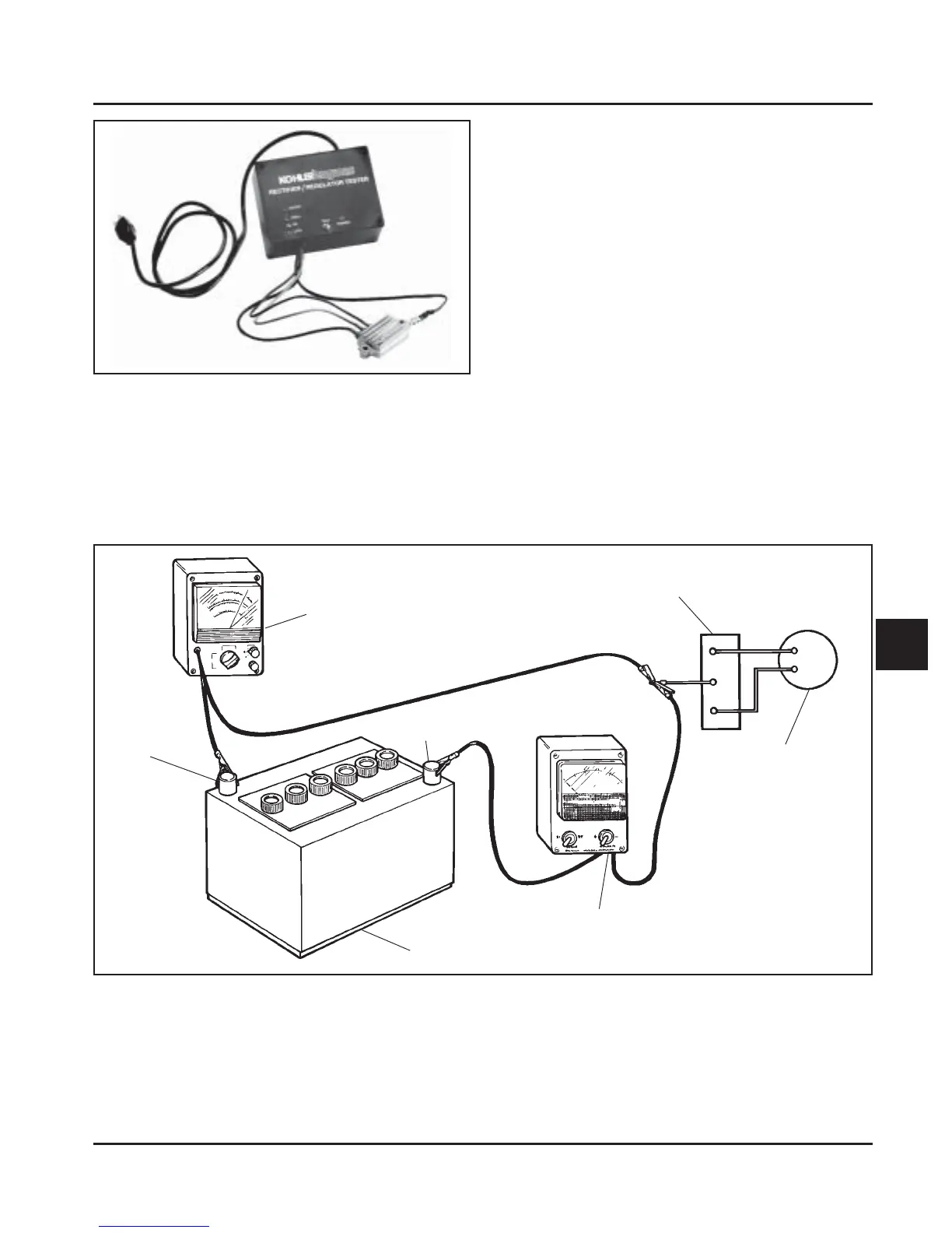
Figure 8-33. Connections for Testing Charging System.
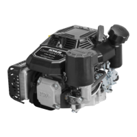
Figure 8-32.
3. Plug the tester into the proper AC outlet/power
supply for tester being used. Turn on the power
switch. The ‘‘POWER’’ light should be
illuminated and one of the four status lights may
be on as well. See Figure 8-26. This does not
represent the condition of the part.
4. Press the ‘‘TEST’’ button until a “click” is heard
and then release. See Figure 8-27. Momentarily
either the ‘‘HIGH’’, ‘‘LOW’’, or ‘‘SHORT’’ light
will flash.
a. If the “HIGH” light flashes on/off, the part is
good and may be used.
b. If any other light is displayed* the rectifier is
faulty and should not be used.
*NOTE: A flashing “LOW” light can also occur as a
result of an inadequate ground lead
connection. Make certain connection location
is clean and clamp is secure.
DC Voltmeter
Rectifier-Regulator
Flywheel
Stator
Ammeter
Battery
(-)
(+)
 Loading...