11.23
Section 11
Reassembly
11
3. Connect the governor spring from the throttle
control bracket to the appropriate hole in the
governor lever, as indicated in the applicable
chart. Note that hole positions are counted from
the pivot point of the governor lever.
Governor Lever Governor Spring
High Idle RPM Hole No. Color Code
3801-4000 6 Clear
3601-3800 5 Clear
3451-3600 4 Clear
3301-3450 3 Clear
3101-3300
5
Purple
2951-3100 4 Purple
2800-2950 3
Purple
3750* 4 Clear
3150* 4
Purple
Governed Idle Hole
6
5
4
3
2
1
*5% Regulation (others 10%)
6 mm Governor Lever and Hole Position/
RPM Chart
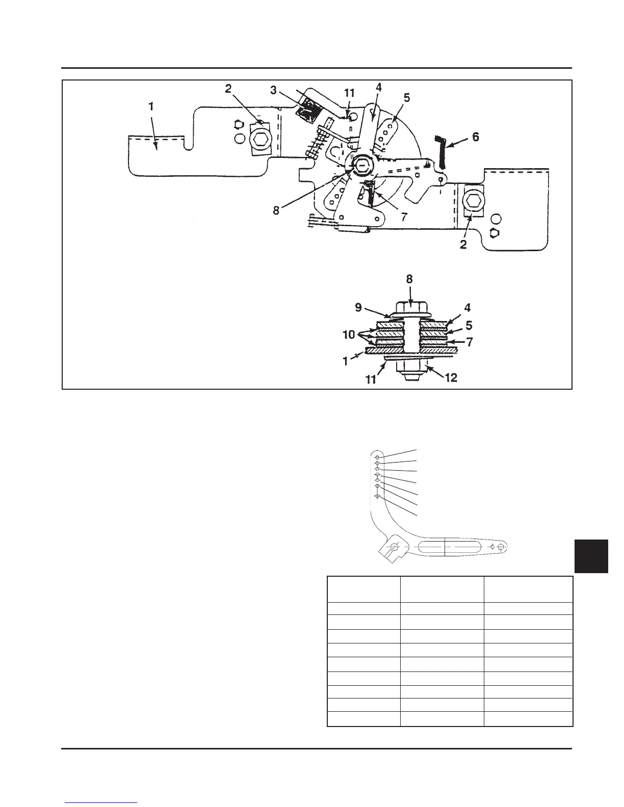
Figure 11-78. Throttle/Choke Control Bracket Detail.
Item Description
1 Bracket, speed control
2 Clamp, cable (some applications)
3 Kill Switch (some applications)
4 Lever, choke (top position)
5 Lever, throttle control (middle)
6 Linkage, choke control
7 Lever, throttle actuator (bottom)
8 Screw, M5x0.8x20
9 Washer, wave
10 Washer, flat (3)
11 Spring, choke return
12 Nut, M5x0.8 lock
 Loading...