9.11
Section 9
Disassembly
9
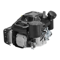
Figure 9-39. Position of Ignition Modules.
3. Remove the mounting screws and ignition
modules. Note the position of the ignition
modules.
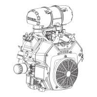
Remove Intake Manifold
1. Remove the four hex flange screws securing the
intake manifold to the cylinder heads. Note
which screws hold the wiring clamps.
2. Remove the intake manifold and the intake
manifold gaskets (aluminum intake manifolds) or
O-Ring (plastic intake manifolds). See Figure
9-40.
3. Leave the wiring harness attached to the
manifold.
Figure 9-40. Removing Intake Manifold.
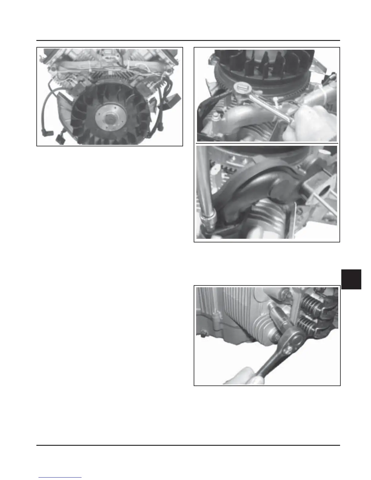
Remove Spark Plugs
1. Remove the spark plug from each cylinder head.
See Figure 9-41.
Figure 9-41. Removing Spark Plugs.
Aluminum
Intake
Manifold
Plastic Intake
Manifold
 Loading...