11.14
Section 11
Reassembly
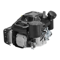
Figure 11-46. Setting Ignition Module Air Gap.
6. Torque the screws to 4.0-6.2 N·m (35-55 in. lb.).
7. Repeat steps 4 through 6 for the other ignition
module.
8. Rotate the flywheel back and forth checking for
clearance between the magnet and ignition
modules. Make sure the magnet does not strike
the modules. Check the gap with a feeler gauge
and readjust if necessary. Final air gap:
0.280/0.330 mm (0.011/0.013 in.).
Install Intake Manifold
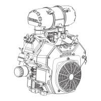
1. Install the intake manifold and new gaskets or
O-Rings (plastic manifold), with wiring harness
attached, to the cylinder heads. Slide any wiring
harness clips onto the appropriate bolts before
installing. Make sure the gaskets are in the proper
orientation. See Figures 11-47, and 11-48. Using
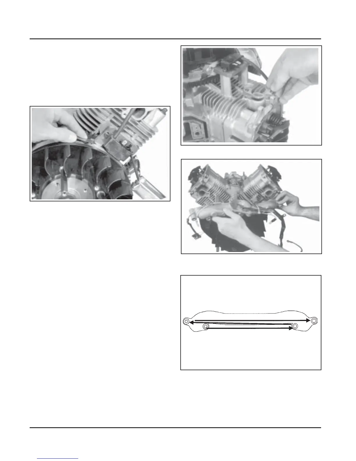
the sequence shown in Figure 11-49, torque the
four screws in two stages, first to 7.4 N·m
(66 in. lb.), then to 9.9 N·m (88 in. lb.).
Figure 11-48. Installing Intake Manifold with Wiring
Harness (Aluminum Manifold Shown).
4. Rotate the flywheel to position the magnet
directly under one ignition module.
5. Insert a 0.30 mm (0.012 in.) flat feeler gauge
between the magnet and the ignition module (see
Figure 11-46). Loosen the screws enough to allow
the magnet to pull the module against the feeler
gauge.
Figure 11-47. Installing Intake Manifold Gaskets.
Figure 11-49. Intake Manifold Torque Sequence.
1
2
3
4
 Loading...