11.13
Section 11
Reassembly
11
Figure 11-47. Cylinder Head Screws Torquing
Sequence.
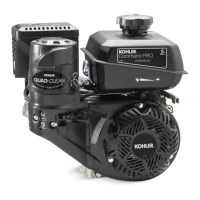
Install Push Rods and Rocker Arms
NOTE: Push rods should always be installed in the
original location.
1. Identify the proper position of each push rod.
Dip the ends of the push rods in engine oil and
install them in their respective locations, seating
each into the tappet socket. See Figure 11-48.
3
1
4
2
Figure 11-48. Installing Push Rods.
2. Install the push rod guide plate, aligning
the holes for the rocker arm studs. Screw in
the rocker arm studs and torque to 13.6 N·m
(120 in. lb.).
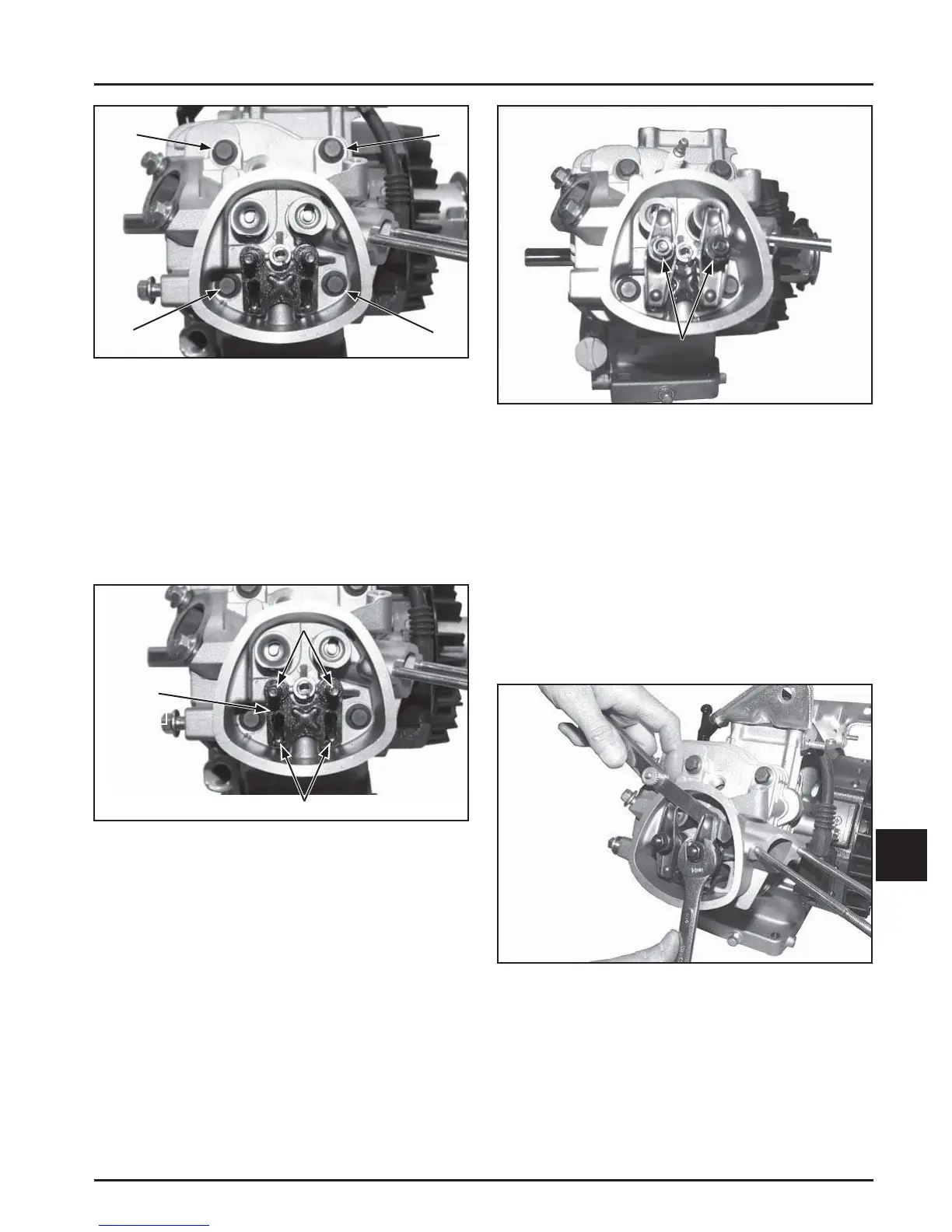
3. Assemble the rocker arms, adjusters, and
locknuts onto the studs and push rods. Finger
tighten the rocker arm pivot jam locknuts. See
Figure 11-49.
Guide
Plate
Rocker Arm
Studs
Install Push Rods
Figure 11-49. Installing Rocker Arms, Adjusters
and Locknuts.
4. Adjust the valve tappet clearance as follows:
a. Make sure the piston is still at the top of the
compression stroke.
b. Insert a fl at feeler gauge between the rocker
arm and the valve stem. The recommended
valve to rocker arm clearance for both intake
and exhaust is 0.076-0.127 mm (0.003-0.005 in.)
(Cold). See Figure 11-50.
Figure 11-50. Adjusting Valve to Rocker Arm
Clearance.
c. Adjust clearance as required by loosening the
locknut and turning the adjuster.
Turn clockwise to decrease clearance.
Turn counterclockwise to increase clearance.
Jam
Locknuts
 Loading...