11.1
Section 11
Reassembly
11
Section 11
Reassembly
General
NOTE: Make sure the engine is assembled using
all specifi ed torque values, tightening
sequences, and clearances. Failure to observe
specifi cations could cause severe engine wear
or damage. Always use new gaskets.
Typical Reassembly Sequence
The following sequence is suggested for complete
engine reassembly. This procedure assumes that all
components are new or have been reconditioned, and
all component subassembly work has been completed.
The sequence may vary to accommodate options or
special equipment. Detailed procedures can be found
in subsequent subsections.
1. Install crankcase bearings and oil seals.
2. Install governor assembly.
3. Install Oil Sentry™ system.
4. Install cranksha .
5. Install connecting rod with piston and rings.
6. Install balance sha .
7. Install valve tappets and camsha .
8. Install closure plate.
9. Install stator
10. Install fl ywheel.
11. Install ignition module.
12. Assemble cylinder head.
13. Install cylinder head.
14. Install push rods and rocker arms.
15. Install valve cover.
16. Install fuel tank supports and shut down switch
with bracket.
17. Install carburetor.
18. Install engine shrouds and air cleaner base.
19. Install electric starter and control panel
20. Install blower housing.
21. Install retractable starter.
22. Install thro le link, governor lever, governor
spring and thro le lever.
23. Install Oil Sentry™ module.
24. Install fuel tank.
25. Install carburetor cover.
26. Install muffl er and heat shield assembly.
27. Install air cleaner element and cover.
28. Prepare engine for operation.
29. Testing the engine.
Install Crankcase Bearings and Oil Seals
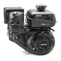
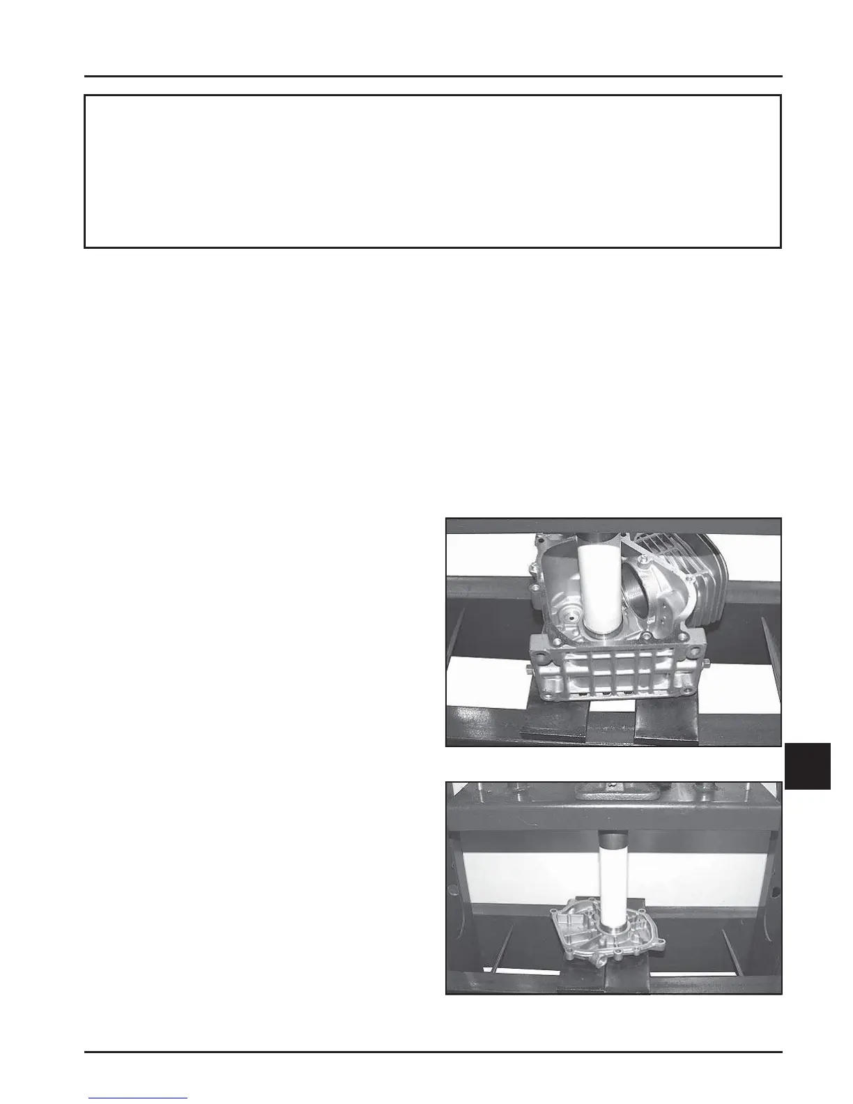
1. Make sure there are no nicks, burrs, or damage
in the bores for the bearings. The crankcase (see
Figure 11-1) and closure plate (see Figure 11-2)
must be clean.
2. Use an arbor press to make sure the bearings are
installed straight into their respective bores, until
fully seated.
NOTE: Oil the bearings liberally with engine oil
when installing.
Figure 11-1. Installing Crankcase Main Bearing.
Figure 11-2. Installing Closure Plate Main Bearing.
 Loading...