11.19
Section 11
Reassembly
11
2. Pull the rope handle to engage the pawls and
center the starter to the drive cup. Hold in this
position and torque the mounting screws to
5.4 N·m (48 in. lb.).
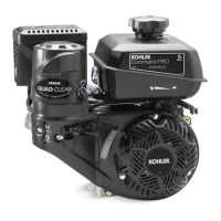
Install Throttle Link, Governor Lever,
Governor Spring, and Throttle Lever
1. Connect the thro le linkage and dampening
spring to the arm of the governor lever as shown.
See Figure 11-74.
Figure 11-75. Governor Lever Adjustment.
Governor
Shaft
Governor
Lever
Throttle Linkage
Dampening
Spring
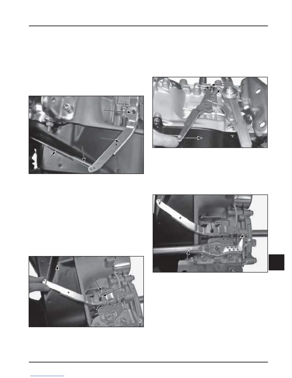
CH395, CH440
3. Push the governor lever in the direction indicated
in Figure 11-76 and hold in this position. Turn the
governor sha counterclockwise until it stops.
Tighten the hex fl ange nut on the governor lever
clamp bolt to lock the lever on the sha . Torque
the nut to 12 N·m (106 in. lb.).
Figure 11-76. Governor Lever Adjustment.
4. Install the spring on the governor and thro le
levers in the holes previously marked in
disassembly. Install the thro le lever and a fender
washer on the threaded stud of the fuel tank
bracket. See Figures 11-77 and 11-78.
Push
Lever
Tighten
Nut
Turn
Governor
Shaft
Push
Lever
Tighten
Nut
Turn
Governor
Shaft
Figure 11-74. Governor Lever Installation.
2. Install the governor lever onto the sha .
Assemble the screw and locknut, but do not
tighten. See Figure 11-75.
CH270
3. Push the governor lever in the direction indicated
in Figure 11-75 and hold against the stop. Turn
the governor sha clockwise until it stops.
Tighten the hex fl ange nut on the governor lever
clamp bolt to lock the lever on the sha . Torque
the nut to 12 N·m (106 in. lb.).
Figure 11-77. Install Throttle Lever for CH270.
Throttle Lever
Spring
 Loading...