11.22
Section 11
Reassembly
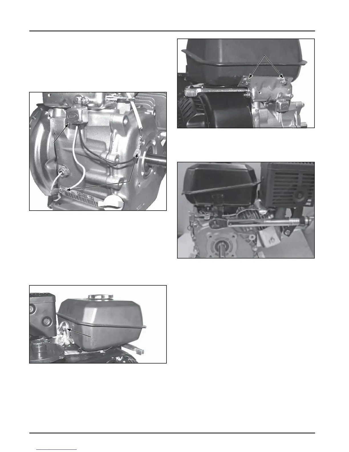
Oil Sentry
TM
Module
Wire
Connections
Figure 11-81. Installing Fuel Tank.
2. Install two hex fl ange nuts on the fuel tank studs.
See Figure 11-82.
Hex Screw
Figure 11-82. Installing Fuel Tank Hardware.
3. Torque the side strap screw to 10 N·m (89 in. lb.).
See Figure 11-83.
Hex Nuts
Figure 11-83. Torque Side Strap Screw.
4. Torque the remaining screw and nuts to 24 N·m
(212 in. lb.).
5. Position the fuel line in the clip on the bo om
of the tank. Connect the fuel line to the shut-
off valve on the carburetor and secure with the
clamp. See Figure 11-84.
Figure 11-80. Reconnect Electrical Leads.
2. Connect the electrical leads for the Oil Sentry™
module. See Figure 11-80.
Install Fuel Tank
1. Position the fuel tank on the mounting brackets.
Secure with hex screws on the inner mounting
bracket and on the PTO side strap. See Figure
11-81.
Install Oil Sentry™ Module
NOTE: If the Oil Sentry™ module is mounted inside
the control panel, skip this step.
1. Install the Oil Sentry™ module and secure with
one hex screw. See Figure 11-80. Torque the screw
to 3.5 N·m (31 in. lb.).
 Loading...