11.11
Section 11
Reassembly
11
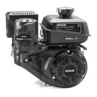
Figure 11-42. Setting Ignition Module Air Gap.
4. Insert a 0.254 mm (0.010 in.) fl at feeler gauge
between the leg of the module and the magnet.
Loosen the nearest screw allowing the magnet to
draw the module against the feeler gauge. Push
against the module to hold the leg tight against
the feeler gauge while tightening the screw. See
Figure 11-42.
5. Rotate the fl ywheel until the magnet is under the
other leg of the module. Loosen the nearest screw
allowing the magnet to draw the module against
the feeler gauge. Push against the module to
hold the leg tight against the feeler gauge while
tightening the screw.
6. Torque the fi rst hex fl ange screw, then the second
hex fl ange screw. Go back and torque the fi rst hex
fl ange screw one more time. Torque both module
screws to 10 N·m (89 in. lb.).
7. Rotate the fl ywheel back and forth, checking to
make sure the magnet does not strike the module.
8. Connect the kill wire to the ignition module
bo om blade terminal and route the wire lead to
the top of the crankcase. See Figure 11-43.
Magnet
Feeler
Gauge
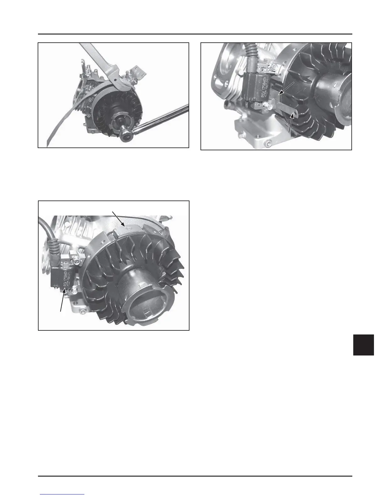
Figure 11-41. Install Ignition Module.
2. Install the ignition module loosely to the bosses
with the two hex fl ange screws. Move the module
as far away from the fl ywheel as possible, then
tighten the screws just enough to hold it in
position. See Figure 11-41.
NOTE: Ensure the ignition module is correctly
oriented.
3. Rotate the fl ywheel until the magnet is under one
leg of the ignition module. See Figure 11-42.
Initial Magnet Location
Initial Module
Location
Figure 11-40. Torque Flywheel Nut.
Install Ignition Module
1. Turn the fl ywheel so the magnet is away from
the location where the ignition module will be
installed. See Figure 11-41.
 Loading...