11.23
Section 11
Reassembly
11
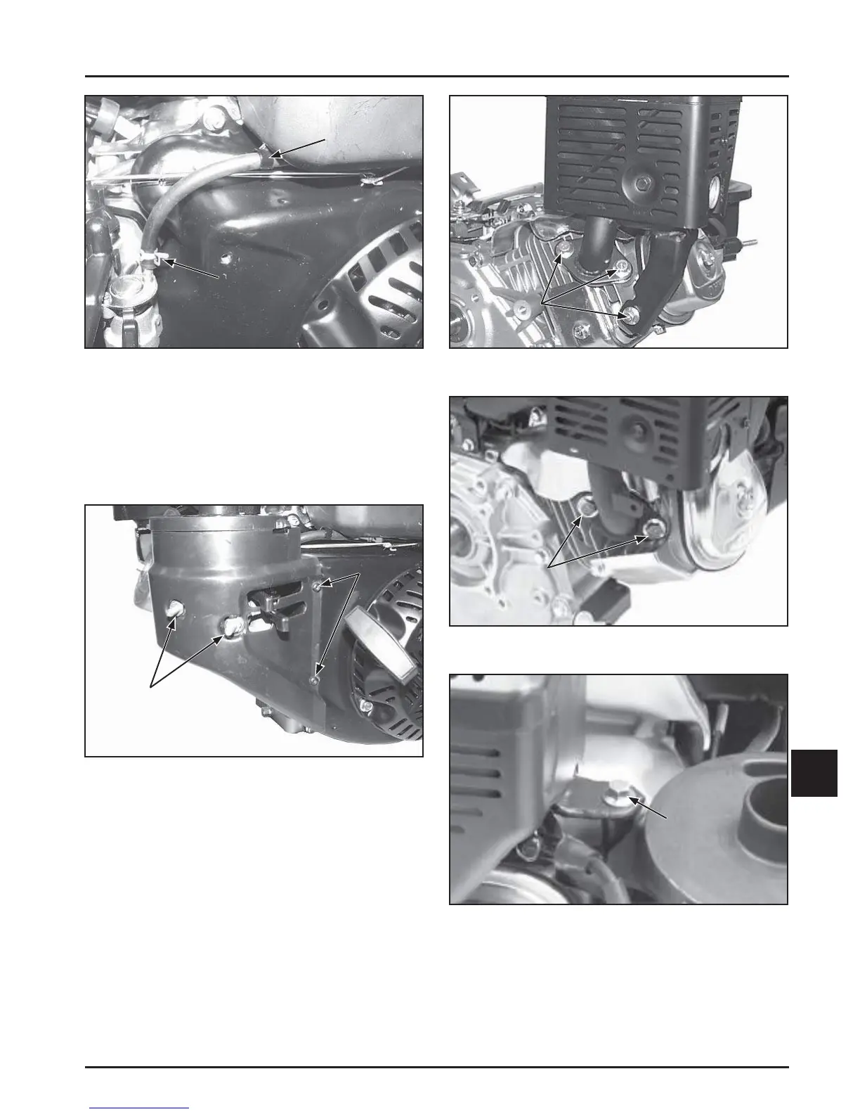
Figure 11-84. Connecting Fuel Line.
Install Carburetor Cover (If Equipped)
1. Install the outer air cleaner cover onto the studs,
over the carburetor. Secure with two hex nuts and
two screws. Torque the nuts to 4 N·m (35 in. lb.)
and the screws to 1.3 N·m (12 in. lb.) See Figure
11-85.
Fuel Line
Clip
Fuel Line
Clamp
Figure 11-85. Installing Carburetor Cover.
Install Muffl er and Heat Shield Assembly
1. Install a new exhaust gasket onto the exhaust
studs.
2. Position the muffl er and heat shield assembly
and install one hex fl ange screw in the support
bracket and two hex fl ange screws in the exhaust
outlet fl ange. See Figures 11-86, 11-87, and 11-88.
3. Torque three hex fl ange screws to:
CH270 24 N·m (212 in. lb.)
CH395, CH440 35 N·m (310 in. lb.)
Hex Nuts
Screws
Figure 11-86. Install CH270 Muffl er/Heat Shield
Assembly.
Hex
Screws
Figure 11-87. Install CH395, CH440 Muffl er/Heat
Shield Assembly.
Figure 11-88. Install CH395, CH440 Muffl er/Heat
Shield Support Hex Flange Screw.
Hex
Screws
Support
Hex
Screw
 Loading...