8.3
Section 8
Electrical System and Components
8
Electronic Ignition System
These engines are equipped with a dependable magneto breakerless ignition. In such a system, electrical energy
is generated by the cu ing of magnetic fl ux lines generated from the ignition magnet on the engine fl ywheel via
the prescribed air gap as it passes the ignition module. This energy is transferred through the ignition module
laminations and is then converted in the module electronics and stored in the module primary coil, as a current
if it is an inductive discharge ignition (IDI) module, or as a voltage in a compacitor if it is a capacitive discharge
ignition (CDI) module. The stored energy is transferred at the correct moment by triggering a semiconductor
switch inside the module. The electrical break by the switch initiates the energy transfer by causing the collapse
of the magnetic fi eld at the coil primary. This includes a voltage at the coil primary that is amplifi ed via
transformer action at the coil secondary. The amplitude of the voltage at the coil secondary is suffi cient to jump
the gap at the spark plug, igniting the fuel air mixture in the gap and initiating combustion. Note that by design,
these modules only will provide proper function if mounted in the correct orientation.
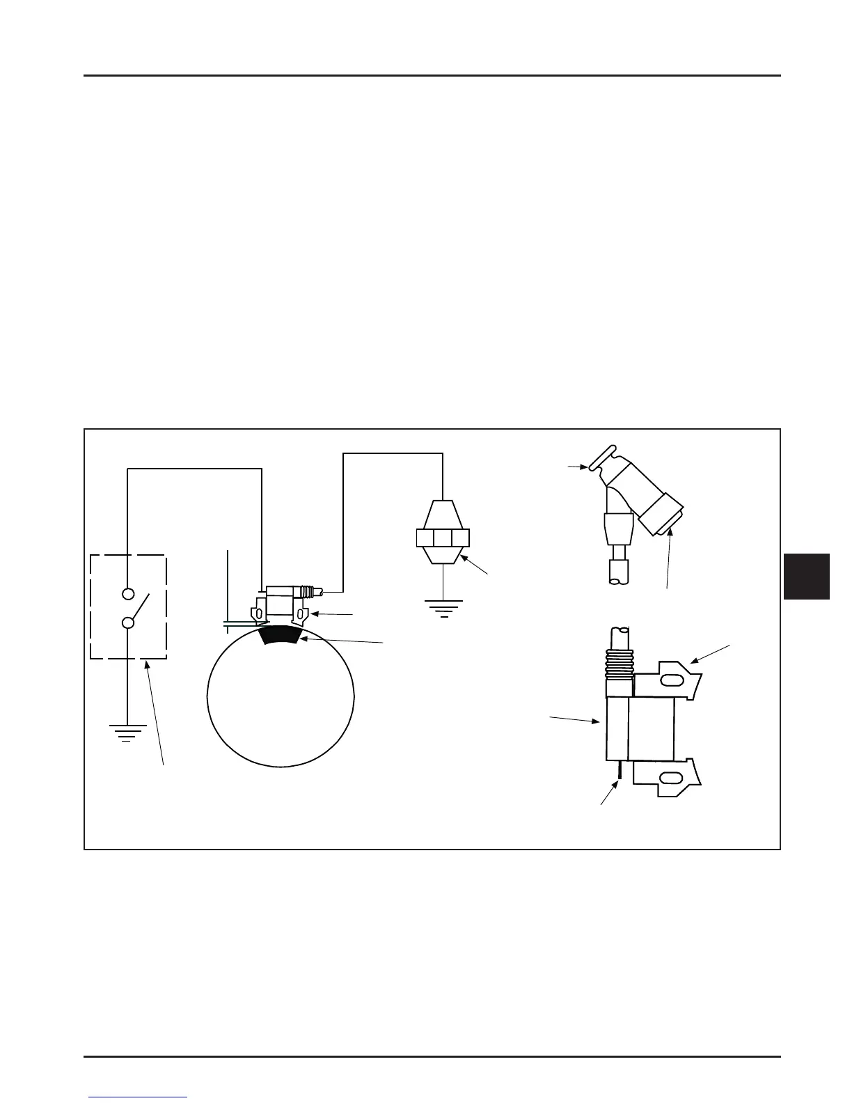
This system consists of the following components (see Figure 8-2):
● Magnets permanently affi xed to the fl ywheel.
● Inductive discharge ignition module (IDI) mounted on the engine crankcase.
● Includes a shut down (kill) terminal mounted at the side of the module.
● Includes a secondary lead wire from the coil to a terminal inside a spark plug boot.
● External switch that connects to the shut down terminal and grounds the module to stop the engine.
Spark Plug
Kill Switc h o r Of f
Position of Key Switch
Air Gap
0.254 mm
(0 .0 1 0 in.)
Flywheel
Magnet
Ig nition
Module
Kill Te rmina l
Ignition Module
(En larged View )
Spark Plug
Te r min a l
Lamination
Spark Plug Boot
Figure 8-2. Inductive Discharge Ignition System.
Troubleshooting and Testing Ignition
Ignition and Oil Sentry™ Systems
Ignition problems are most o en due to poor or loose
connections, or connections that keep the shut down
terminal shorted to ground preventing proper ignition
operation.
Before beginning any test procedures, be certain
all module terminal connections are correct and
fi t snugly. Make certain the shut down lead is not
shorted to ground when the engine is a empting
to crank or run. Proper ignition module air gap to
the fl ywheel magnet must be maintained for best
performance. Ensure crankcase oil is at the proper
level. Refer to Section 6.
 Loading...