125Section 8 Component Testing and AdjustmentTP-6356 4/12
8.2.2 Installation
1. Position the part(s) in place in the same manner
that the old part was installed. Support the back of
circuit boards when installing plug-in parts, such as
relays and wiring harness plugs, to avoid bending
the circuit board.
2. Tighten or reinstall hardware that holds the part(s)
in place to the general torque specifications in
Appendix C, General Torque Specifications,
unless otherwise noted.
If the torque specifications do not cover the
application or do not seem appropriate let common
sense prevail. Avoid overtorquing hardware in
sheet metal and non-metallic composites.
3. Reconnect wiring to the same location from which it
was removed, torquing terminals to the
specifications given in Section 1, Specifications.
8.3 General Information
Use the respective parts catalog to determine the
appropriate replacement part. Sometimes service kits
replace a given part where additional components in the
kit are necessary to provide the functional component
equivalent. The parts catalog illustrations may serve as
a guide for replacement but be aware that multiple
models are generally illustrated in a single view and
details may not represent the specific application.
8.4 Leads/Wires/Wiring Harnesses
Repair/replace wiring when there is any doubt about its
condition. Tape minor control circuit wire insulation cuts
or abrasions less than 1 mm (0.04 in.) across by
wrapping the section tightly with three layers of electrical
tape.
Repair moderately damaged leads, where conductors
are cut or insulation is damaged over sections shorter
than about 100 mm (4 in.) or less than about 25% of the
length of the wire by cutting out the damaged section
and splicing in wire of the same type.
Replace extensively damaged or deteriorated leads
completely. If the leads are part of a wiring harness,
replace entire wiring harness. Fabricate replacement
leads using the same type of wire as the old leads. Add
terminals and lead markers at each end of the new load.
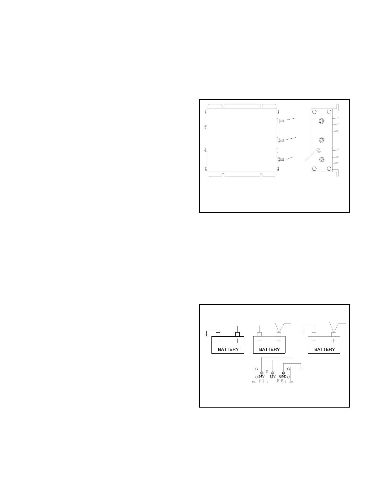
8.5 Battery Equalizer, 135--275 kW
DDC-Powered Gas Models
The 135-275 kW Detroit Diesel Series 50/60 gas models
use a battery equalizer module for balanced battery
charging. See Figure 8-1. The 24-volt engine
(cranking) electrical system provides a 12-volt DC
supply at 20 amps max to the ignition coils, fuel valves,
and DDEC engine electronic control system.
343028
1. +24V—battery 24-volt positive (+) connection (input)
2. +12V—battery 12-volt positive (+) connection (output)
3. Ground—battery negative (--) ground connection
4. 20-amp circuit breaker (manual reset)
1
3
2
4
Figure 8-1 Battery Equalizer
The 135-275 kW Detroit Diesel Series 50/60 gas models
use a three-battery system. See Figure 8-2. The
three-battery system provides a separate 12-volt
battery electrical system that is unaffected by the 24-volt
cranking system voltage drop. See Figure 8-3 the for
battery equalizer specifications.
Refer to the appropriate wiring diagram manual for
battery equalizer electrical connections.
TP-5353-3
1. To starter motor solenoid (24 volts DC)
2. To ignition coils, fuel valves, and engine controls (12 volts DC)
12
BATTERY EQUALIZER
ABC
Figure 8-2 Three-Battery System

 Loading...