197Section 10 Governor AdjustmentsTP-6356 4/12
In the Parameter Select Mode, each press of the INC
key causes the display of the next higher parameter ID.
After the maximum parameter ID is reached, the display
loops back to the first display.
In the Parameter Edit Mode, each press of the INC key
increases the current value. Holding the INC key down
automatically causes the values to rise at an increasing
rate until the INC key is released or the parameter’s
maximum value is reached.
DEC (Decrease) key. Use the DEC key to decrease the
displayed parameter ID or value depending upon mode
selection.
In the Parameter Select Mode, each press of the DEC
key causes the display of the next lower parameter ID.
After the minimum parameter ID is reached, the display
loops back to the last display.
In the Parameter Edit Mode, each press of the DEC key
decreases the current value. Holding the DEC key down
automatically causes the values to fall at an increasing
rate until the DEC key is released or the parameter’s
minimum value is reached.
INC and DEC keys together. In the Parameter Select
Mode, pressing and holding the two keys at the same
time causes the LED segments to go ON. This serves
as a test for the LED segments. Release the keys to
resume displaying the parameter ID number.
In the Parameter Edit Mode, pressing and holding the
two keys at the same time permits viewing the upper two
digits of a 4-digit number. The left digit’s decimal point is
turned on indicating that the thousands and hundreds
digits are displayed.
Note: Not all parameters have four digit values, in which
case the upper digits will display 0.0 (zero
decimal point zero).
Release the keys and the tens and ones digits are again
displayed. The right digit’s decimal point is flashing
when editing is allowed or steady on indicating that
editing is not allowed.
10.5.5 LED Display Functions
(Load Share Model only)
The governor controller LED display provides two
7-segment LEDs with digit’s corresponding decimal
point to display values and indicate mode of operation.
Refer to Figure 10-13 illustration for the load share
model.
When the LED display value flashes, the Parameter
Select Mode is active.
When the LED display value is steady on, the selected
parameter’s value is displayed and the user interface is
in the Parameter Edit Mode. The decimal points also
indicate which half of a 4-digit value is displayed and
whether editing is allowed.
The right digit’s decimal point indicates that the lower
2 digits of a value (tens and ones) are displayed. When
the right decimal point flashes, the values can be
changed using the INC and DEC keys. When the right
digit is steady on, no editing is allowed or is password
protected.
The left digit’s decimal point indicates that the upper
2 digits of a value (the thousands and hundreds) are
displayed. The greater 2 digits are always view only so
the right decimal point does not flash.
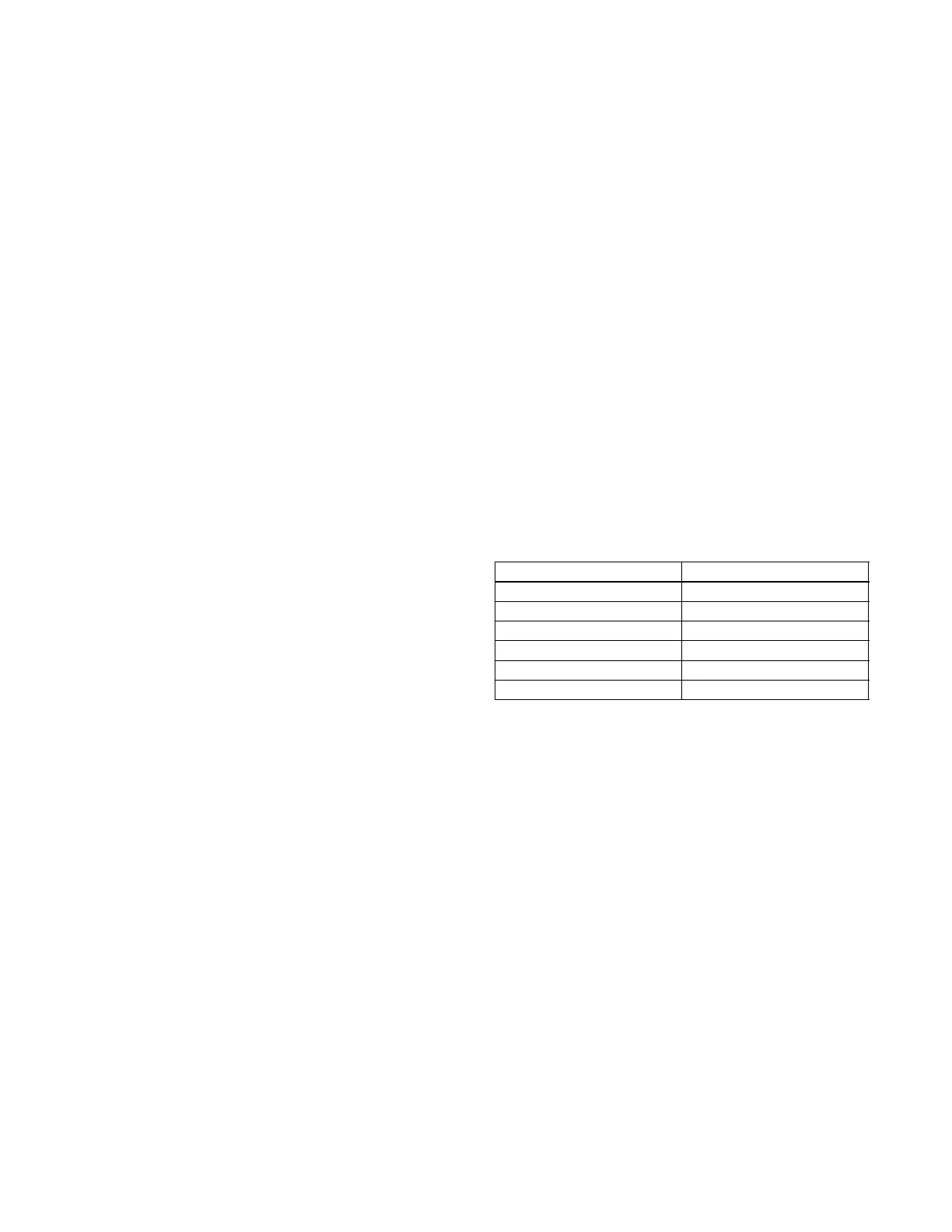
When values exceed four digits, the LED display uses
the hexadecimal numbering system to represent the
value of the thousands position. See Figure 10-15 and
the following examples.
Note: For generator set applications, the values will not
exceed 9999. This text is for informational
purposes only in the event that a value is
inadvertently entered above 9999.
Decimal Value Hexadecimal Equivalent
10 A
11 B
12 C
13 D
14 E
15 F
Figure 10-15 Decimal to Hexadecimal Conversion
Chart
Example A
The desired set value is 10069 Hz. The upper two digits
should display A.0 and the lower two digits should
display 69.
Example B
The desired set value is 10972 Hz. The upper two digits
should display A.9 and the lower two digits should
display 72.
10.5.6 PST Software
The PST software enables the user to adjust parameter
settings and monitor governor operation when a user-
supplied PC is connected to the governor controller via
the COMM port.

 Loading...