128 Section 8 Component Testing and Adjustment TP-6356 4/12
8.7 Crank Relay
The test procedure for the following crank relay applies
to other applications of the same type relay. See
Figure 8-7.
GM14230B-D
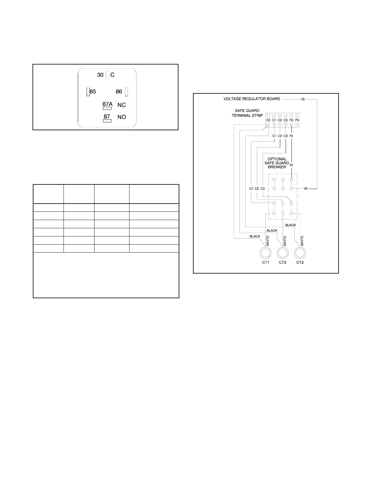
Figure 8-7 Crank Relay Contacts
The relay is a single-pole, double-throw relay. Contacts
85 and 86 are the relay coil. See Figure 8-8 for
specifications by relay part number. If replacement is
necessary, do not substitute part numbers.
Relay Part
Number
Coil
Voltage
VDC
Coil
Resistance,
ohms
NO/NC Contacts
Rating, Amp
259391 12 85 ±5 30/20
272684 24 305 ±15 20/16
GM28787 12 90 ±10 40/20
GM37390 12 90 ±10 40/30
GM49746* 12 90 ±10 50/30
GM49747* 24 360 ±10 50/30
* These relays contain an integrated diode that may affect
ohmmeter values when checking coil resistance. Be sure to
check coil resistance with the ohmmeter leads connected both
ways to help verify relay functionality and prevent unnecessary
replacement.
Note: Relays 259391 and GM28787 are superseded to
GM49746. Relay 272684 is superseded to GM49747.
Figure 8-8 Relay S pecifications
8.8 Current Transformers
8.8.1 Function and Application
The current transformers provide several generator set
functions including signal/drive for:
D Controller AC voltmeter/ammeter
D Safeguard circuit breaker
D Reactive droop compensator
The generator set models do not have current
transformers when they do not include the above items.
The meters and safeguard circuit breaker share the
same current transformer while the reactive droop
compensator uses a separate current transformer.
See Figure 8-9. The generator set junction box contains
the stator leads and the current transformers.
When replacing the current transformer or stator
assembly, i nstall the current transformer according to
the generator reconnection decal on the generator set,
or see the wiring diagrams manual. Observe the correct
current transformer position when installing the stator
leads. The current transformer dot or HI mark position
and the stator lead direction are essential for correct
component function. The dot or HI mark should face
toward the stator.
TT-1123/347058-D
Figure 8-9 Current Transformers
Two styles of current transformers are used. Round
(doughnut) styles have black/white leads with no
mounting provisions. The square styles have two #8-32
studs/nuts for connecting the leads and four notches in
the base for mounting.
A current transformer contains a coil of wire that induces
a secondary voltage/current from the primary or stator
lead passing through the center. The number of coil
turns inside the current transformer determines the
ratio. Replacement current transformers must have the
same ratio as the original.
8.8.2 Testing
Use an ohmmeter to check the current transformer.
Perform this test with the current transformer
disconnected from the generator set. A resistance
reading of infinity or 0 ohms suggests an open or shorted
current transformer that needs replacement. Consider
any other resistance reading acceptable.

 Loading...