133Section 8 Component Testing and AdjustmentTP-6356 4/12
1
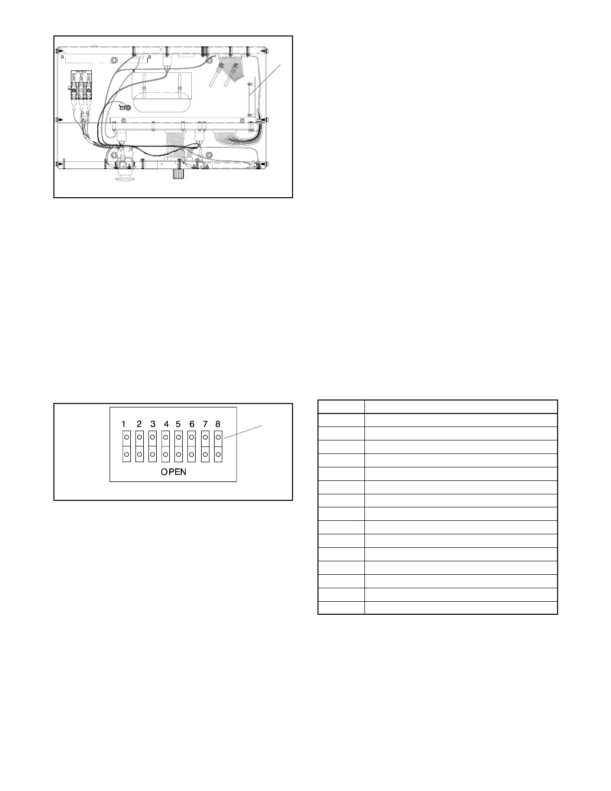
GM10193A-N
1. Pulse converter circuit board
Figure 8-17 Pulse Converter Circuit Board Mounting
in Decision-Makerr 550 Controller (top
view)
DIP Switch
Service technicians should be aware that odd number
tooth counts have an inherent percent error in engine
speed calculations. An even number of flywheel teeth
do not cause the percent error in speed. If the flywheel
has an odd number of teeth, the circuit board logic uses
acorrectionfactorasfollows:
(1 -- [tooth count] / [tooth count + 1]) x 100 = correction value
Use the circuit board DIP switch, see Figure 8-18 to
match the engine flywheel tooth number count.
6126
1. DIP switch closed position
1
Figure 8-18 DIP Switch Positions
Programming Shunt
Use programming shunt J1 across pins 1 and 2 on the
circuit board to get a 1:1 output. The shunt provides a
1:1 output regardless of the DIP switch selection. The
shunt is typically used with the 550 controller and is also
intended as a diagnostic test during troubleshooting.
Place J1 across pins 2 and 3 for a 2-pulse output signal.
Tach Output
The circuit board has a secondary output (P5-4) that
matches the input signal 1:1. Some generator set
models use this connection to eliminate an engine
speed sensor. See Figure 8-16 for P5-4 location.
Air Heater Control
The circuit board provides a 6-minute (ᐔ30 seconds)
signal pulsed on and off at 1 minute intervals to activate
the air heater after the start switch is toggled. If the start
switch signal is interrupted during the 6 minutes, the air
heater control signal is deenergized.
8.11.2 Anticipatory High Coolant
Temperature and Low Oil
Pressure Relays
The circuit board provides dry contacts for anticipatory
high coolant temperature (AHCT) and low oil pressure
(LOP) inputs for some generator set models.
LED Indicator
The red LED will flash at 1 Hz rate if the DIP switch
setting matches the engine flywheel tooth count and the
generator set is running at 60 Hz. The LED indicator
provides some diagnostic help. See Section 8.11.3,
Circuit Board Troubleshooting.
Circuit Board Connections
Figure 8-19 shows the connections made to the pulse
converter circuit board. Some generator set models
may not have all connections.
Plug-Pin Connection
P4-1 Low oil pressure input signal
P4-2 Battery positive (+) lead 70
P4-3 Anticipatory high coolant temperature input signal
P4-4 Cable shield (ground)
P4-5 Magnetic pickup sensor low (ground)
P4-6 Magnetic pickup sensor high
P5-1 Magnetic pickup output signal shield (ground)
P5-2 Speed signal output signal
P5-3 Speed sensor ground
P5-4 Tach output signal
P5-5 Magnetic pickup output signal (ground)
P5-6 V+ Speed sensor
P5-7 Low oil pressure output signal
P5-8 Anticipatory high coolant temperature output signal
P5-9 Air heater output signal
Figure 8-19 Pulse Converter Circuit Board
Connections

 Loading...