131Section 8 Component Testing and AdjustmentTP-6356 4/12
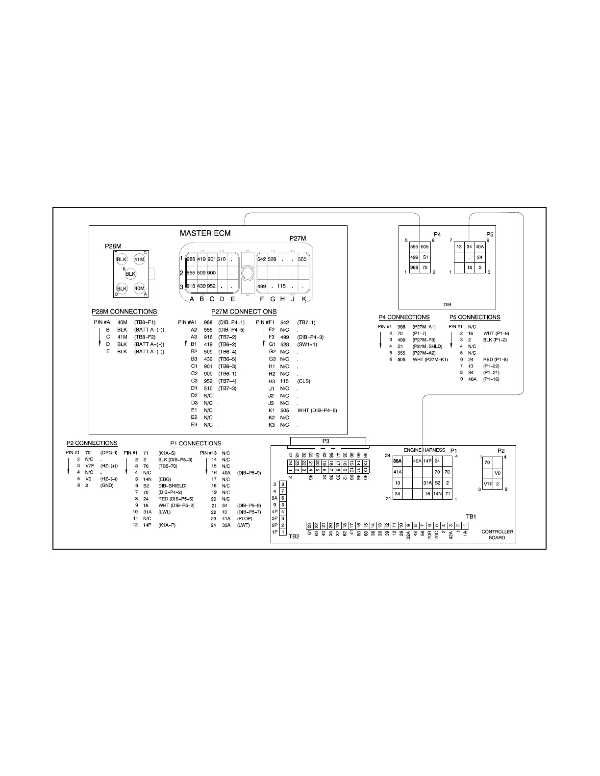
The DIB connects between the DDEC and the 16-light
controller main circuit board. See Figure 8-14. Check
the DIB and its connections for damage and correct
seating when troubleshooting its operation rather than
the following additional switches or sensors that are not
present on the generator set controls equipped with a
DIB.
D Low oil pressure switch
D High engine (coolant) temperature switch
D High engine (coolant) temperature warning switch
D Engine speed sensor
Three relays K1 (LOP), K2 (HET), K3 (PHET), and other
circuitry on the interface circuit board isolate the digital
warning/fault outputs of the DDEC and convert them to a
signal level used by the generator set controller. LED1
(LOP), LED2 (HET), and LED3 (PHET) light and the
corresponding relay coil energizes when the
corresponding input to the generator set controller
signals an engine problem.
The K1 (LOP) relay coil energizes and its contact closes
from the low oil pressure (LOP) switch output to ground
when the DDEC sends a ground signal to the circuit
board on the LOP input. K1 is not used on Series 60
engines.
361264-
Figure 8-14 DDEC Interface Circuit Board Connections
The K2 (HET) relay coil energizes and its contact closes
from the high engine (coolant) temperature (HET)
switch output to ground when the DDEC sends a ground
signal to the circuit board on the HET input.
The K3 (PHET) relay coil energizes and its contact
closes from the high engine (coolant) temperature
warning switch output to ground when the DDEC sends
a +24 VDC battery signal to the circuit board on the
pre-high engine (coolant) temperature (PHET) input.
The DDEC provides a 12 pulse/revolution engine speed
signal. The interface circuit board converts this signal to
a 2 pulse/revolution engine speed signal that is used by
the generator set controller.

 Loading...