172 Section 9 Gas Fuel Systems TP-6356 4/12
Generator
Set Model,
kW
Ford
Engine
Model
Factory Lead Connection Configuration by Fuel Type
Natural Gas LP Gas
Nat. Gas/
LP Gas
Combination
Gasoline/
Natural Gas
Combination
Gasoline/
LP Gas
Combination
Gasoline
18 kW (See
Figure 9-15)
LRG-423 70—Red/Green
7N—Black
7N—Yellow/Black
from pins #6 & #7
70—Red/Green
7N—Black
7N—Yellow/Black
from pin #6
70—Red/Green
7N—Black
7N—Yellow/Black
from pin #6
— — —
18 kW (See
Figure 9-16)
LRG-425 70—Red/Green
70—Yellow/Black
7N—Black
7N—Brown/White
70—Red/Green
7N—Black
7N—Brown/White
70—Red/Green
7N—Black
7N—Brown/White
— — —
20 kW (See
Figure 9-17)
LRG-423
70—Red/Green
7N—Black
7N—Yellow/Black
from pins #6 & #7
70—Red/Green
7N—Black
7N—Yellow/Black
from pin #6
70—Red/Green
7N—Black
7N—Yellow/Black
from pin #6
70—Red/Green
7N—Black
Maintain Yellow/
Black wire loop
70—Red/Green
7N—Black
Maintain
Yellow/ Black
wire loop
70—Red/Green
7N—Black
Maintain
Yellow/ Black
wire loop
20 kW (See
Figure 9-18)
LRG-425 70—Red/Green
70—Yellow/Black
7N—Black
7N—Brown/White
70—Red/Green
7N—Black
7N—Brown/White
70—Red/Green
7N—Black
7N—Brown/White
70—Red/Green
7N—Black
70—Red/Green
7N—Black
70—Red/Green
7N—Black
— Fuel system not available
Note: All colored leads are part of the ignition module harness. Tape to insulate the exposed end of all unused leads.
Note: Lead 70 is 12 volts DC positive (+) and energized during engine run. Lead 7N is the ground connection.
Note: LRG-425 engines only
Brown/White lead connects to lead 7N for gas fuels only.
Yellow/Black advances timing 5_ when connected to lead 70.
Yellow/Black retards timing 3_ when connected to lead 7N.
Note: The LP gas data above applies to LP gas vapor and LP liquid withdrawal fuel systems.
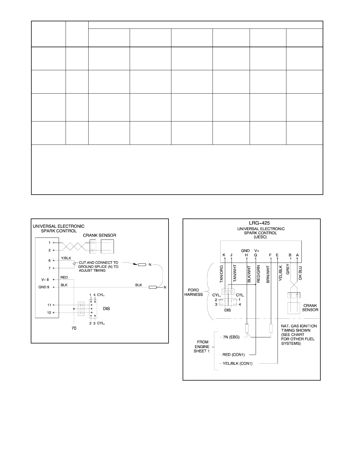
Figure 9-14 Factory Lead Connection Configurations
326457-A
Figure 9-15 18 kW with LRG-423 Engine
326870B-
Figure 9-16 18 kW with LRG-425 Engine

 Loading...