179Section 9 Gas Fuel SystemsTP-6356 4/12
80--125 kW Models (8.1 L GM Engine). Use the
following procedure, except Step 5. Refer to the
respective specification sheet for generator set ratings
based on fuel selection.
1. Remove the generator set from service.
a. Place the generator set master switch in the
OFF position.
b. Disconnect the power to the battery charger, if
equipped.
c. Disconnect the generator set engine starting
battery(ies), negative (--) lead first.
d. Close all fuel supply valves.
2. Replace the gas mixer and regulator for LP gas
vapor (80--125 kW models only).
a. Remove the components from the engine as
shown in Figure 9-32.
D Remove the four screws attaching the gas
mixer to the throttle. The 80 kW has the
screw heads accessible from the bottom and
the 100/125 kW have the screw heads
accessible from the top. Retain the gasket
between the gas mixer and throttle.
D Disconnect the fuel line at the union
connector.
D Remove the supporting clamp between the
fuel regulator and mixer.
b. Disconnect the piping from the gas mixer inlet
and fuel regulator inlet and outlet.
c. Apply pipe thread compound to all male
threads and assemble the fuel system
assembly with the new gas mixer, reducer
bushing, and fuel regulator supplied in the kit.
d. Place the gas mixer on the throttle with the
existing gasket and install the four screws. See
Figure 9-34.
e. Reconnect the fuel line at the union connector.
3. Set up the fuel regulator for LP gas (30 kW model
with 3.0 L engine only).
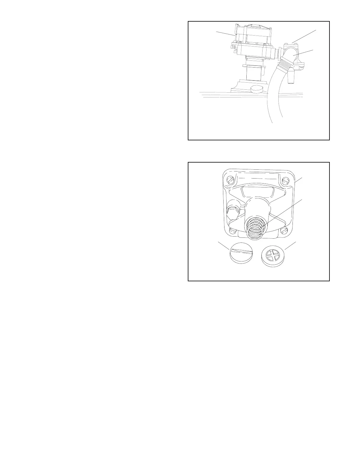
a. Rotate the fuel regulator to a downward
pointing position as shown in Figure 9-34.
b. Remove the cover plug and adjustment screw
from the fuel regulator. See Figure 9-35.
GM14257-C
1. Fuel mixer
2. Fuel regulator (downward position)
3. Fuel line elbow
1
2
2
Figure 9-34 Fuel Mixer, Typical
SB-527
1. Fuel regulator
2. Spring
3. Adjustment screw
4. Cover plug
1
2
34
Figure 9-35 Fuel Regulator, Typical
c. Remove the spring. The spring will not be
reused.
d. Replace the adjustment screw to the
approximate midpoint of the adjustment range.
e. Replace the cover plug.
4. Change the fuel configuration jumper wire at
junction box terminal strip
Follow the procedure for the respective model.
See Figure 9-36 for a summary of all fuel
configurations requiring the TB12 terminal strip.
The fuel and frequency jumper connections on
TB12 is also available in the respective Wiring
Diagram Manual.

 Loading...