3.
After checking that the hydraulic oil temperature has drop-
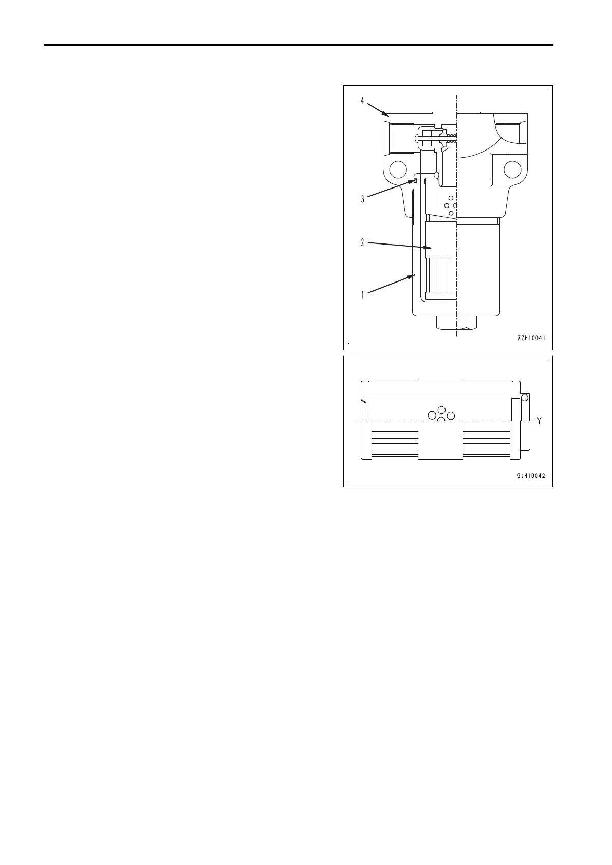
ped, turn filter case (1) counterclockwise, remove it, then
remove element (2).
4.
Clean the removed parts, then install new element (2).
REMARK
Element (2) must be installed facing in the correct direc-
tion. Set direction (Y) with the holes in it up, and fit the hole
in element (2) on the protruding part inside filter head (4).
5.
Install a new O-ring (3) to filter case (1), then tighten filter
case (1).
Tightening torque: 25 to 35 Nm {2.6 to 3.6 kgm}
SPECIFICATIONS
Hydraulic specifications
•
Max. flow when merged: 275×2 ℓ/min
• Safety valve relief set pressure of service valve
Port A: 21.6 MPa {220 kg/cm
2
} (other than mode B)
Port B: 24.5 MPa {250 kg/cm
2
} (other than mode B)
• Safety valve cracking pressure of service valve
Port A: 17.2 MPa {175 kg/cm
2
} (other than mode B)
Port B: 20.1 MPa {205 kg/cm
2
} (other than mode B)
•
Safety valve relief set pressure of service valve: 21.6 MPa {220 kg/cm
2
} (mode B)
•
Safety valve cracking pressure of service valve: 17.2 MPa {175 kg/cm
2
} (mode B)
HANDLE MACHINE READY FOR INSTALLATION OF ATTACHMENT ATTACHMENTS AND OPTIONS
6-32

 Loading...